— —
Navigation

Send Us A Message
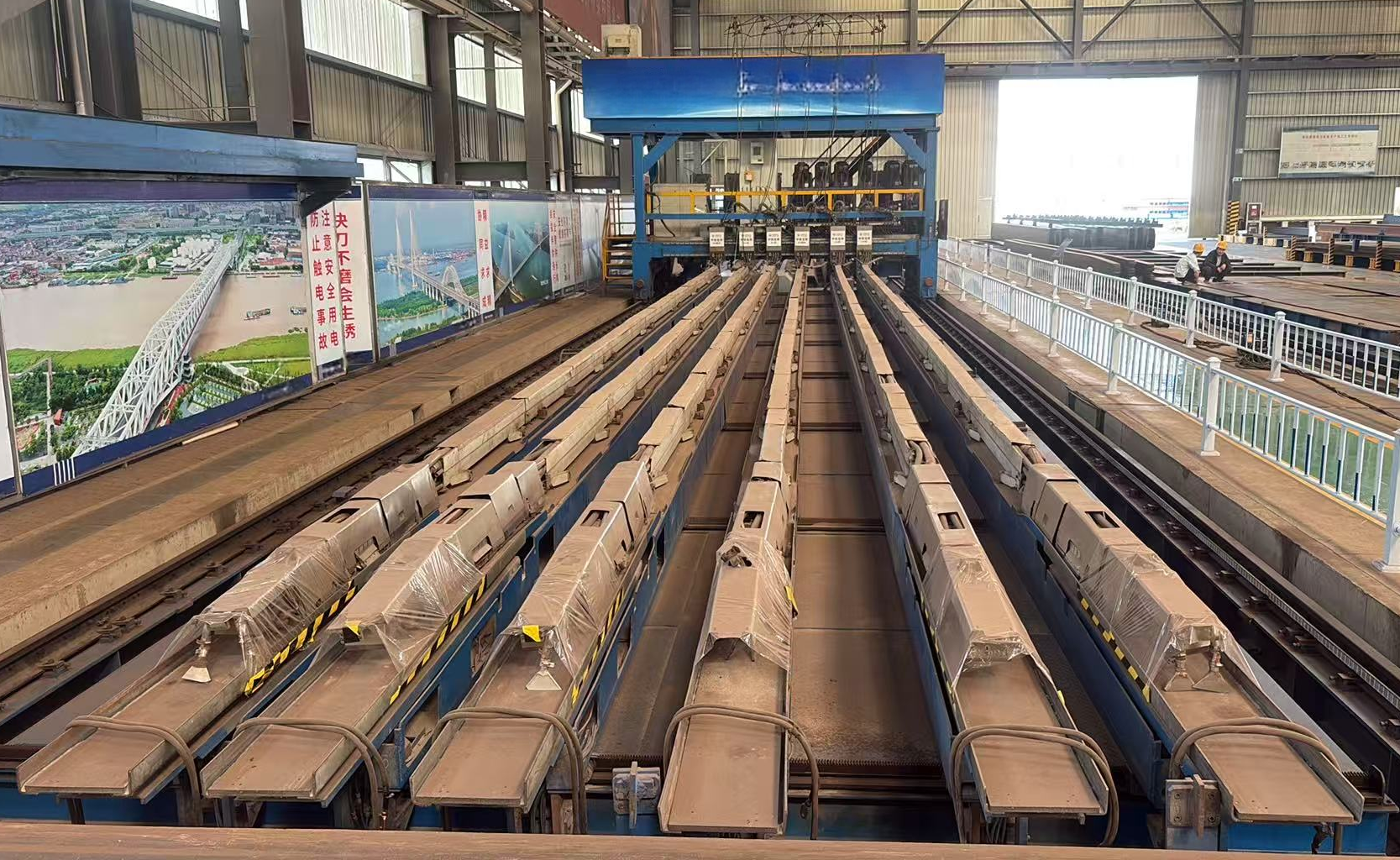
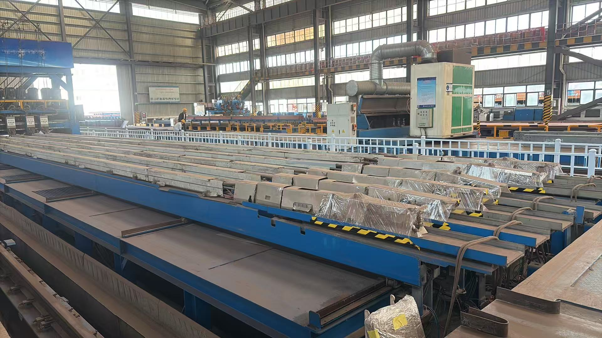
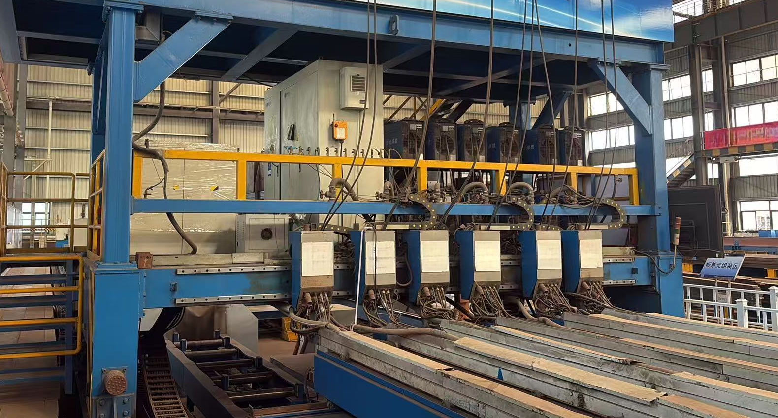
U Rib inside welding machine
Product Parameters
1.Introduction for U Rib inside welding machine:
1.1Overview
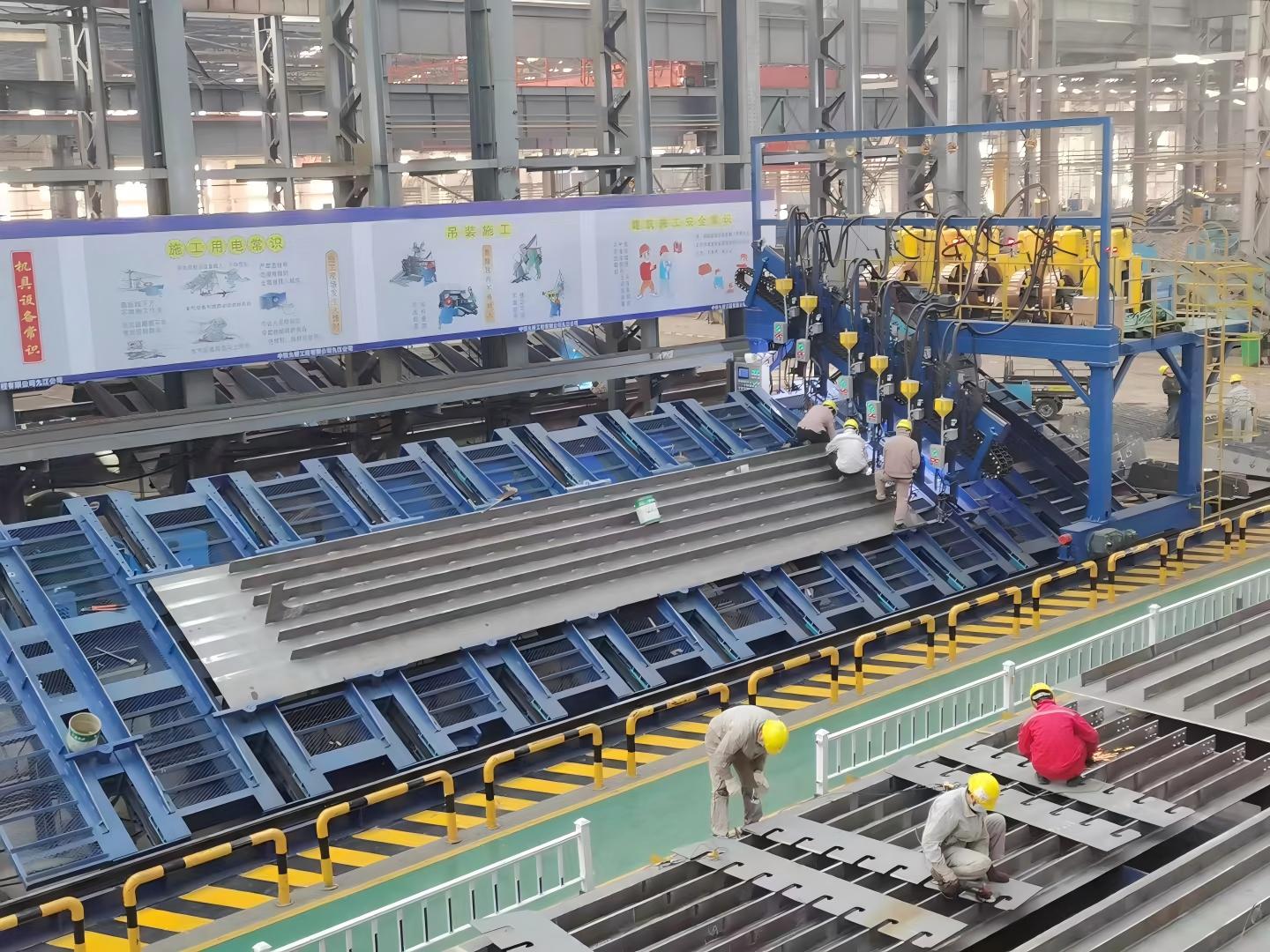
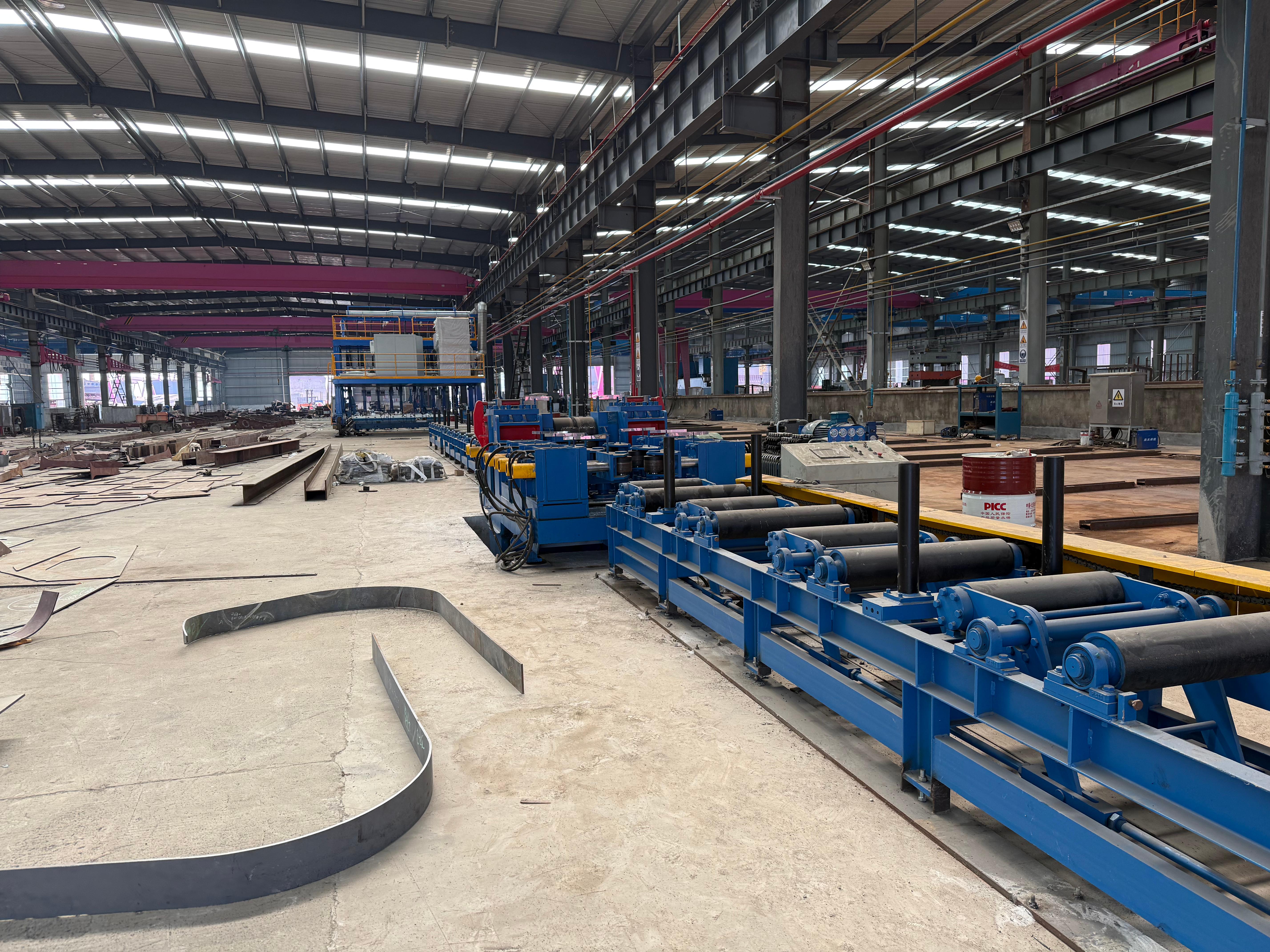
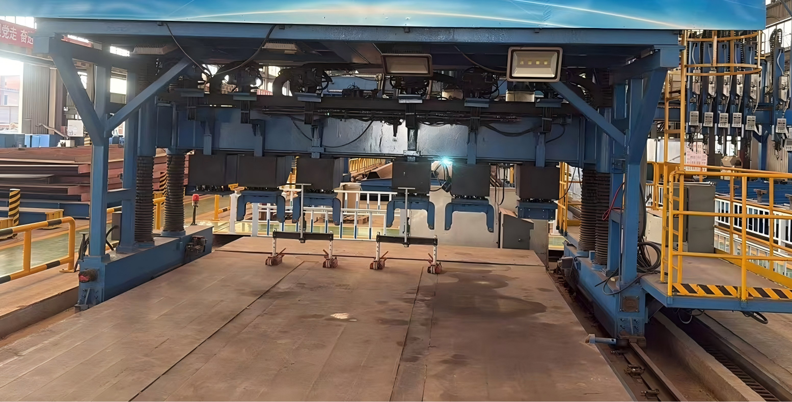
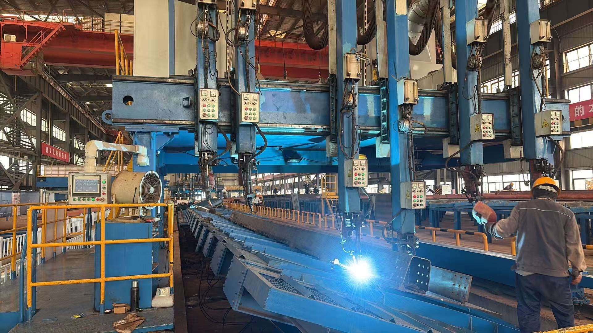
This system mainly consists of 6 sets of automatic welding arms for internal U-rib welds, and 1 gantry welding frame (including 12 welding machines, gas supply system, power supply system, wire feeding system, electrical control system, 6 adjustable welding arm moving tracks, 1 hydraulic plate unit automatic centering and clamping positioning system, and 1 software system).
2.Technical parameter for U Rib inside welding machine:
2.1Processing Range of U Rib Plate Unit
2.2The main performance of the internal welding system of the bridge U-beam
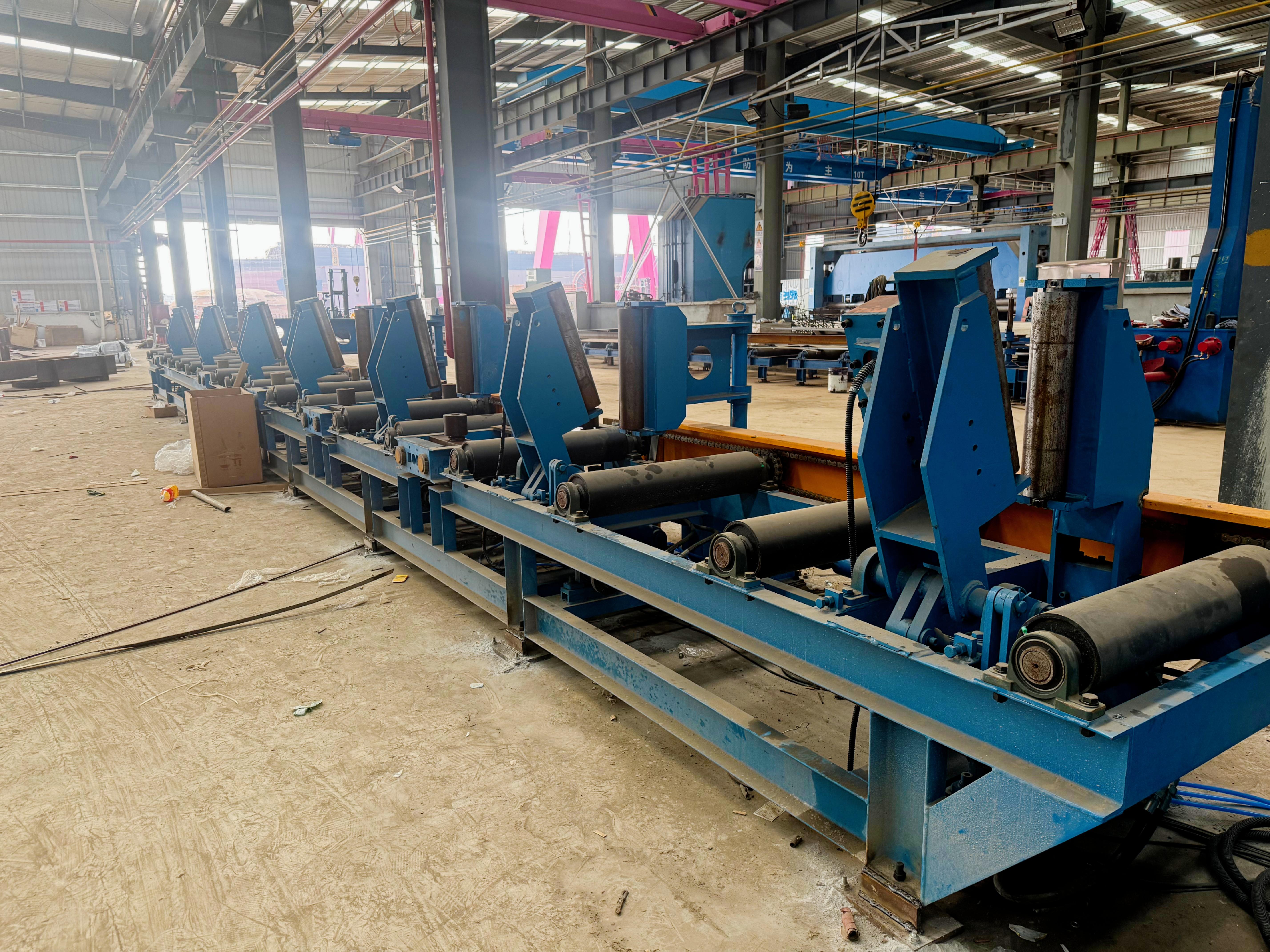
1 set hydraulic automatic plate alignment and pressing positioning systemAfter assembled U‑rib plate units are hoisted onto the equipment, the automatic alignment and positioning system is activated. Hydraulic actuators drive the plate unit to align automatically and abut against one positioning edge. The pressing device is then engaged to clamp and secure the plate unit.
1 gantry welding frame (gantry fixed type optional)The gantry welding frame serves as the base of the system. It is fitted with 12 welding machine units, gas supply system, power supply system, wire feeding system and electric control system. It provides driving power for U‑rib internal welding and integrates all pipelines and control connections.
6 automatic welding arms for U‑rib internal fillet weldsEach U‑rib internal fillet welding arm is equipped with two welding torches. The arm enters inside the U‑rib to deliver welding wire over long distance, recover flux, supply welding power and perform seam‑tracked welding. During operation, both torches work simultaneously to reach the welding zone and automatically complete fillet welding on both inner sides of the U‑rib.
6 adjustable moving tracks for welding armsEach adjustable track provides a travelling path for the U‑rib internal fillet welding arm. The tracks and corresponding welding arms can be individually disassembled or re‑spaced. Adjustment of one unit will not interrupt the operation of other welding arms.
1 control systemThe system supports centralized automatic control and manual control. It governs the hydraulic plate alignment & pressing positioning system, defines welding start and stop positions, enables automatic equipment operation, and regulates welding current, voltage and welding speed.
2.3Workpiece requirements
The width of the base plate ranges from 1.8m to 4.5m, the maximum length of the base plate is 18m, and the thickness of the base plate is 12 to 40 mm. The thickness of the U-rib plates is 6 to 12 mm. The U-ribs do not have bevels or have bevels with a blunt edge of 4 mm. Each base plate can accommodate a maximum of 6 U-ribs. The height of the U-ribs is 260mm to 280mm, the width of the lower opening of the U-ribs is 300mm to 400mm, and the center spacing of the U-ribs is 600 to 800mm. The material of the workpiece is Q345 to Q370.
2.4Welding process requirements:
The internal welding system of the U-beam of this bridge uses solid welding wire, with a diameter of 1.6mm. The actual weld fillet size can reach a range of K = 6mm - 9mm (for one weld). The double-sided fillet welds inside the U-beam are formed smoothly and beautifully. The specific welding process shall be based on the welding process approved by the contractor.
2.5Technical performance parameters
2.6Scope range
2.7User-provided spare parts (including test equipment supplies)
3.Characters for U Rib inside welding machine:
3.1 Summary of Technical Solutions
In order to meet the requirements of welding the internal corner welds of the bridge U-ribs, our company has developed the bridge U-rib internal welding system. This system can meet the needs of welding the internal corner welds of the U-ribs of the bridge plate units, significantly reduces the manufacturing cost of the bridge plate unit components, greatly improves the work efficiency, and greatly enhances the fatigue life of the bridge U-rib corner welds. It leads the advancement of the manufacturing technology of bridge plate units. The technical solution of the bridge U-rib internal welding system is as follows:
1) Lift the assembled U-rib unit components onto the automatic alignment and clamping positioning device of the hydraulic plate unit.
2) Start the automatic alignment and clamping positioning system of the hydraulic plate unit, and the U-rib unit components will automatically align and be clamped.
3) After the plate unit components are clamped, the gantry welding machine frame drives 6 U-rib internal weld joint arms to enter the U-rib interior of the plate unit components and move to the other end of the U-rib.
(Or use the welding gantry for fixation and move the welding clamping platform for internal weld joint welding.)
4) Start the internal welding system of the U-rib, and the equipment will complete the welding of all 6 U-rib internal bilateral weld joints in one go.
5) During the welding process, the welding video monitoring system can display the welding status in real time.
6) After the internal weld joints of the plate unit U-rib are welded, transfer them to the flipping jig for external weld joint welding.
7) After the plate unit is welded, transport it to the inspection area for inspection of the internal and external weld joints.
8) After the U-rib plate unit components are inspected and repaired, lift them onto the U-rib plate unit correction machine for correction.
9) After the U-rib plate unit is corrected, transfer it to the next process.
3.2 Overview of Key Features
The internal welding system for bridge U-ribs is a brand-new welding equipment, with the following main features:
1) It is the first to achieve fully automatic welding of the internal corner welds of bridge U-ribs.
2) It can simultaneously weld the corner welds on both sides of 6 U-ribs at once, with high welding efficiency.
3) Only 1-2 people are needed to operate this system, with high automation and good welding quality.
4) The U-rib plate unit pieces achieve automatic alignment and compression positioning, with fast speed and high efficiency.
5) The internal welds are welded using welding, with large penetration depth and high strength. Combined with the external welding, the penetration rate can reach 100%, significantly improving the service life of the bridge steel structure.
Related products
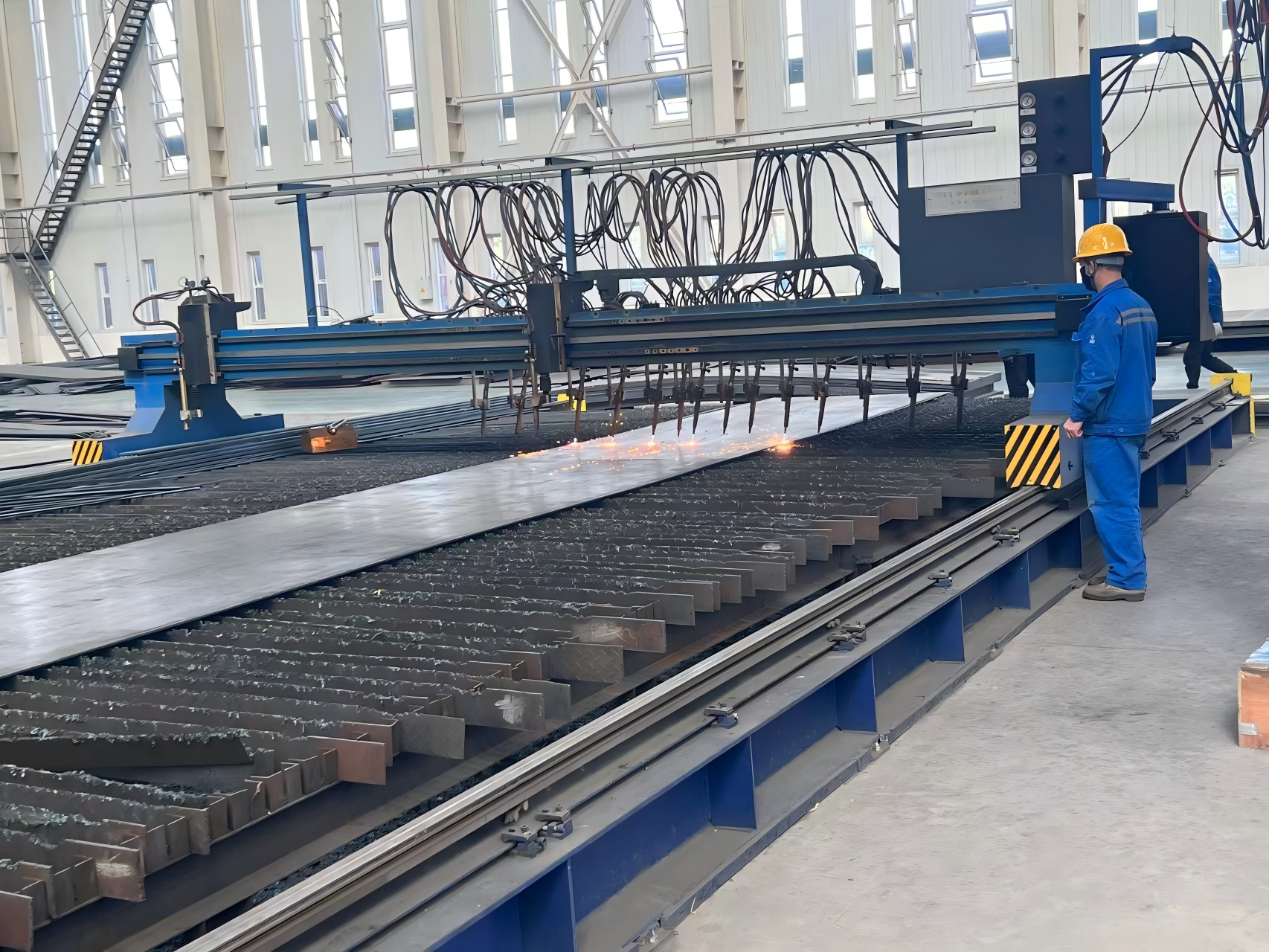
 GZ-6000 CNC flame cutting machineGZ type CNC flame cutting machine integrates CNC, precision mechanical transmission and oxygen-gas cutting technologies. This high-efficiency, high-precision and reliable thermal cutter can cut various shapes including straight lines, arcs and combined non-circular curves on the X-Y plane. Composed of control system, drive system and control cabinet, it is easy to operate and maintain. Widely applied in steel structure factories, shipbuilding, construction, heavy machinery, boiler, petrochemical and locomotive industries.
 T beam flange chamfering machineThis machine adopts rolling principle to form rounded corners on workpiece blank edges efficiently. It replaces traditional manual deburring and chamfering, delivering uniform rounded corners with nice surface finish and high productivity while cutting down labor intensity. Edge rolling greatly reduces stress concentration on sheet edges. It benefits sheet welding, anti-corrosion treatment and avoids paint peeling. Suitable for both mass and small-batch production, it is ideal matching equipment for ship plate beveling.
 T beam assembly machineThis T-shaped profile assembly machine positions flange and web in two steps. It features centering pre-positioning, one-sided positioning with hydraulic floating clamping and lifting wheel for uneven plates. Equipped with AC variable frequency drive, it ensures tight fitting of workpieces and stable operation.
 T beam welding machineThis gantry welding machine performs automatic welding for pre-formed T-shaped steel. It adopts servo-driven automatic seam tracking welding arm and linear moving gantry. Equipped with fume treatment system and heavy-duty welding platform with hydraulic clamping and anti-flipping devices, it controls welding deformation and guarantees operation safety.
 T beam straightening machineThis machine adopts die pressing and mechanical reverse deformation principles to eliminate upward arching deformation and restore stress deformation of T-profiles, featuring high precision and high efficiency. It is suitable for both mass and small-batch production, serving as ideal supporting equipment for ship T-profile manufacturing.
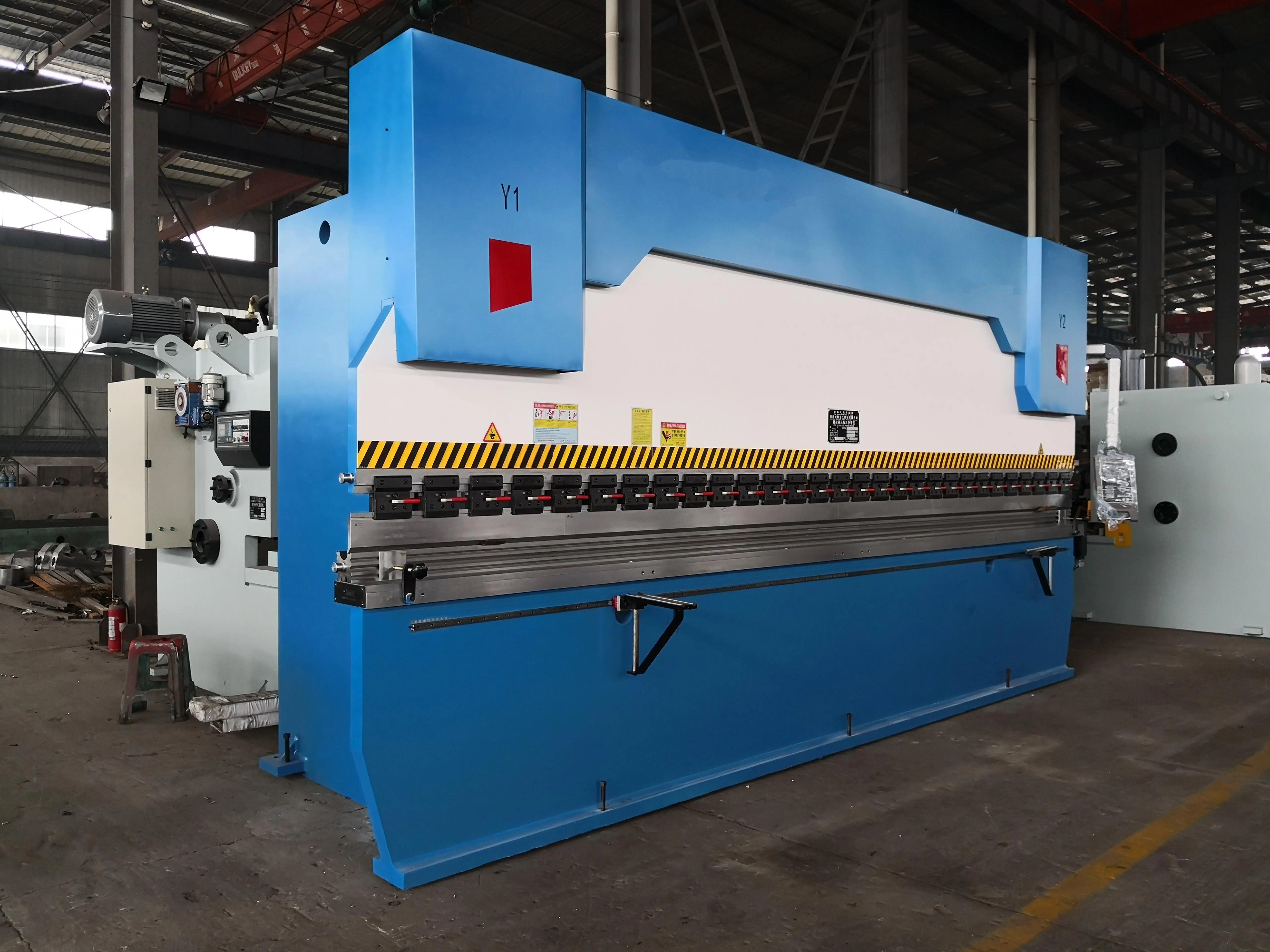
The T-profile straightening station consists of a T-beam straightening machine and front & rear floating roller tracks. The straightening machine corrects panel angle, upward arching and side bending deformation, while the floating roller tracks realize stable workpiece transportation during straightening. U Rib Press BrakeSpecial CNC press brake for bridge U rib forming. Twin machine linkage available. Multi-language CNC, proportional valve hydraulic system, automatic mechanical crowning, European safety standard. Ideal for steel box girder U stiffener production.
 U Rib assembly machineU‑RIB assembly machine is designed to tightly press U‑ribs onto base plates for accurate alignment and gap elimination at mating surfaces. Manual positioning and spot welding can be carried out at joints of six U‑ribs and base plates. It comprises travelling frame, travelling tracks, integrated U‑rib pressing module, hydraulic system and manual welding system.
 U Rib Outside welding machineThis U‑rib portal outside welding machine carries out simultaneous gas‑shielded sub‑boat fillet welding for multiple U‑ribs and base plates. Equipped with bilateral drive, 6 sets of seam trackers, tiltable lifting beam (0~±38°), PLC control and digital centralized welding parameter adjustment, it delivers high welding efficiency with compact structure and easy operation.