




— —
Where does a railway type welding robot improve weld coverage?
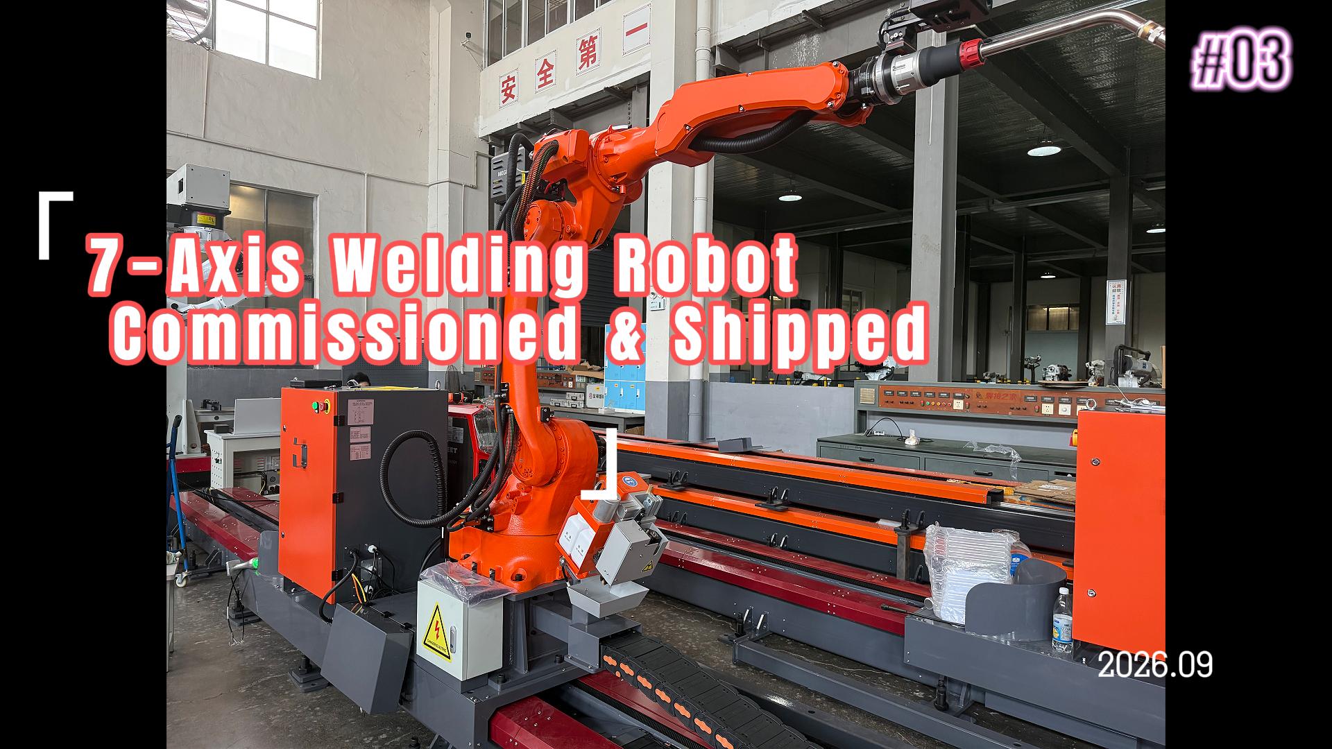
A railway type welding robot improves weld coverage most clearly on workpieces where the weld path is long enough for travel consistency to matter and stable enough for a programmed torch path to be repeated. Typical examples include H-beams, box beams, crane girders, cross beams, bridge subassemblies, rail vehicle frames, and large structural frames assembled on fixed fixtures. In these applications, coverage is not simply the length of weld deposited. It is the ability to reach the specified seam continuously, maintain the required bead profile, and complete the same joint geometry across a production batch without leaving inaccessible starts, stops, or inconsistent sections.
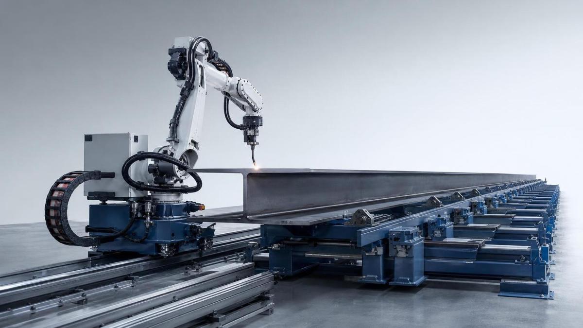
The rail-mounted arrangement is especially effective when the part is too large to reposition frequently. Instead of moving a heavy assembly through multiple manual stations, the welding head travels along a guided axis beside or above the workpiece. This creates a controlled relationship between the torch, the seam, and the fixture. Long fillet welds on beam flanges and webs are a common example: the robot can follow the joint from end to end while keeping torch angle, travel speed, wire feed, and arc conditions within the programmed range.
Longitudinal seams on structural steel members
H-beam fabrication is one of the strongest coverage applications. A beam often contains long web-to-flange joints that are repetitive in form but demanding in duration. Manual welding may require several starts and stops because of shift changes, repositioning, fatigue, or access limitations around clamps and supports. Each interruption introduces a possible overlap, crater, insufficient tie-in point, or variation in bead shape. A railway type welding robot reduces these interruptions by carrying the welding process across the available rail length in one controlled sequence.
Coverage gains are most meaningful when the beam geometry remains within a defined family. If web height, flange width, joint preparation, and fixture datum are reasonably controlled, a program can be reused with only limited adjustment. If each beam arrives with a different offset, camber, tack weld condition, or plate fit-up, the rail alone will not correct the problem. The robot may still travel accurately while the actual joint moves away from the intended torch position. Therefore, the improvement comes from the combination of guided travel and stable fabrication references.
For box beams and closed structural members, rail-guided welding also improves access along outer corner seams and long stiffener joints. These welds are often awkward because the torch must maintain a suitable approach angle while the workpiece occupies substantial floor space. A moving robotic carriage can keep the torch in a repeatable orientation without requiring repeated rotation of the entire assembly. The result is particularly useful where part handling is slower or more disruptive than the welding cycle itself.
Coverage where access changes along the joint
Some seams are technically visible but difficult to weld consistently because access changes from one end to the other. Brackets, diaphragms, stiffeners, gusset plates, connection plates, and reinforcing members can interrupt a long seam or restrict the torch approach near the ends. A railway type welding robot improves coverage when its travel axis and manipulator reach allow it to pass these locations without forcing a major repositioning.
This does not mean every obstructed joint is suitable for rail-guided automation. The relevant question is whether the obstacle pattern is repeatable and whether the torch can approach the joint without collision. A regular sequence of stiffeners can be included in a programmed path, with planned arc stops, weave changes, or altered approach positions. Randomly placed temporary tabs, irregular tack welds, loose cable loops, and inconsistent clamps create a different problem: they consume the clearance that the robot needs for dependable travel.
End regions deserve separate attention. Weld coverage near beam ends is often reduced by fixture blocks, lifting lugs, run-on tabs, or the limited reach of a torch mounted at a fixed carriage position. A process that produces excellent welds through the central length but leaves short manual sections at both ends has not fully solved the coverage issue. Rail length, torch stroke, work holding arrangement, and the intended use of run-on and run-off plates should be reviewed together. The usable welding envelope is smaller than the nominal rail length whenever stops, buffers, cable management, or safety clearances occupy part of the travel.
Repetitive frame assemblies and rail components
Large fabricated frames frequently contain families of similar welds spread along a long base structure. Examples include underframe members, longitudinal reinforcement, equipment support rails, and repeated transverse connections. Here, coverage improves because the robot can move between programmed positions without re-establishing manual alignment at every joint. The advantage is strongest when the frame remains on a fixture and the rail is referenced to the same datum used for assembly.
Rail components present a related but distinct application. Long rail-associated fabrications, such as support frames, maintenance structures, crossover assemblies, or rail vehicle structural parts, often require extended weld paths with constrained access. The robot is valuable where the seam is geometrically stable and the workpiece can be held against movement from welding heat. It is less suitable when the component must be continuously manipulated to expose changing weld positions, unless the cell also includes a positioner designed around that sequence.
Joint orientation matters as much as seam length. A long flat-position fillet weld is usually a better automation candidate than a shorter overhead or heavily obstructed weld. Where a rail system can maintain a favorable position through most of the seam, coverage and bead consistency tend to improve together. Where the torch must repeatedly transition between flat, vertical, and overhead positions around complex geometry, programming and access verification become the limiting factors.
Why fit-up determines whether coverage is real
A robot can deposit metal over a planned route, yet the completed weld may not cover the joint adequately if the gap or alignment changes along the member. This is one of the most common sources of incorrect expectations. Rail travel accuracy governs where the carriage moves; it does not automatically guarantee that the arc remains centered on an actual joint with variable fit-up.
For long structural seams, review the following fabrication conditions before judging the likely coverage improvement:
- Web-to-flange alignment: A consistent web position gives the torch a stable seam reference. Progressive lateral drift can turn a centered fillet program into one that favors one plate edge.
- Root gap and plate contact: Gap changes alter heat demand and bead volume. A parameter set that fills a tight section may underfill a wider section or create excessive reinforcement where plates close together.
- Tack weld shape and spacing: Tacks that protrude into the planned travel line can disturb torch clearance, arc stability, or seam tracking. Their placement should match the automated path rather than be treated as an independent preparation task.
- Thermal restraint: Long members can pull or bow as welding progresses. If the fixture does not control movement, the seam position at the far end may differ from its position at the start.
Seam tracking can compensate for limited positional variation where the system is configured for it and the joint provides a readable reference. It should not be used as a substitute for basic fit-up control. Heavy scale, spatter, unstable tack profiles, reflective surfaces, or sharply changing joint geometry can reduce tracking reliability. The most dependable arrangement uses accurate fixturing first, then applies tracking to manage normal production variation.
Prepared faces and downstream weld access
Weld coverage begins before the arc is started. End-face condition, beam squareness, and the quality of prepared contact surfaces influence whether components locate correctly in fixtures and whether connection areas remain accessible for subsequent welding. Where beam or column members require face milling before assembly, a Standard NC Face milling machine can be incorporated into the preparation sequence for H-beams, box beams, and cross beams. A properly referenced face supports more repeatable assembly positioning; it does not replace control of the longitudinal weld joint, but it reduces one source of cumulative dimensional error.
The relationship is important on assemblies that use end stops or datum blocks to position a long member under the rail. If the end face is out of square, the workpiece can enter the fixture with a slight angular error. Over a long seam, that error may become large enough to affect torch-to-joint alignment. Face preparation should therefore be considered alongside rail straightness, fixture datum placement, and the programmed coordinate system.
Where a rail system has limited benefit
A railway type welding robot is not automatically the best route to higher coverage on small, highly variable fabrications. Short welds scattered across many unrelated parts can consume more time in loading, locating, and program selection than they save in arc travel. Similarly, parts with frequent design changes may require fixture and program revisions before consistent coverage is achieved.
Very complex three-dimensional joints can also change the calculation. A rail gives excellent linear reach, but a linear axis does not by itself create access around deep pockets, internal corners, or compound curves. The robot wrist, torch geometry, external axes, collision zone, and cable routing must all be evaluated against the actual part model. A long rail does not compensate for a torch that cannot enter the joint at the required angle.
Another limitation is poor workpiece reference control. If assemblies are placed directly on the floor, supported on uneven blocks, or shifted by inconsistent crane handling, each setup can begin from a different location. The robot will repeat its own coordinates accurately while missing the intended seam reference. In such conditions, fixture improvement often produces a larger coverage gain than expanding robot travel.
Setting the welding envelope before installation
The useful question during layout is not simply how long the rail should be. It is where the torch must start, stop, retract, clear fixtures, and receive service access. The installation envelope should include the longest workpiece, the highest expected member, the widest attachment, and the space required for loading and unloading. It should also account for welding cables, wire supply, fume extraction interfaces, and the protected travel zone around moving equipment.
Rail straightness and support condition influence repeatability over long distances. Settlement beneath the rail, uneven anchoring, or damage to the travel surface can create small positional deviations that become visible in a narrow joint. These issues may appear first as inconsistent stick-out, changing bead placement, or intermittent tracking corrections rather than as an obvious carriage fault. Inspection should include the mechanical rail condition as well as the welding program.
For long seams, the programming sequence should include planned lead-in and lead-out behavior. Arc initiation at a cold start can differ from deposition after sustained travel, while termination may leave a crater if the sequence is not controlled. Run-on and run-off tabs are often useful where permitted by the fabrication process because they move start and stop effects away from the functional joint. Their placement must remain clear of the robot path and any clamping arrangement.
Maintaining coverage through production changes
Coverage is not fixed once a cell has been commissioned. Changes in plate thickness, wire type, welding position, joint preparation, or fixture components can alter the effective process window. A program that remains dimensionally correct may still need revised travel speed, torch angle, weaving, or arc settings to maintain the desired bead form. Treating a new workpiece as merely a different length of the same part is a common source of avoidable rework.
Routine observation should focus on the seam itself: whether the bead remains centered, whether the toes tie into both members, whether starts and stops are sound, and whether access remains unchanged after fixture maintenance. When a defect repeats at the same rail position, inspect rail condition, cable drag, and local obstruction. When it repeats at the same feature on every workpiece, inspect the joint design, tack pattern, and programmed path. Those two patterns look similar from a distance but point to different corrective actions.
Rail-guided welding delivers its strongest coverage improvement where the fabricated assembly is long, the joint pattern is stable, and the workholding establishes a reliable reference. Under those conditions, the robot turns extended seam length from a manual constraint into a controlled travel path, while leaving complex or variable areas visible as separate process decisions rather than hidden sources of inconsistency.
