




— —
How does a Mig welding robot reduce spatter in repetitive joints?
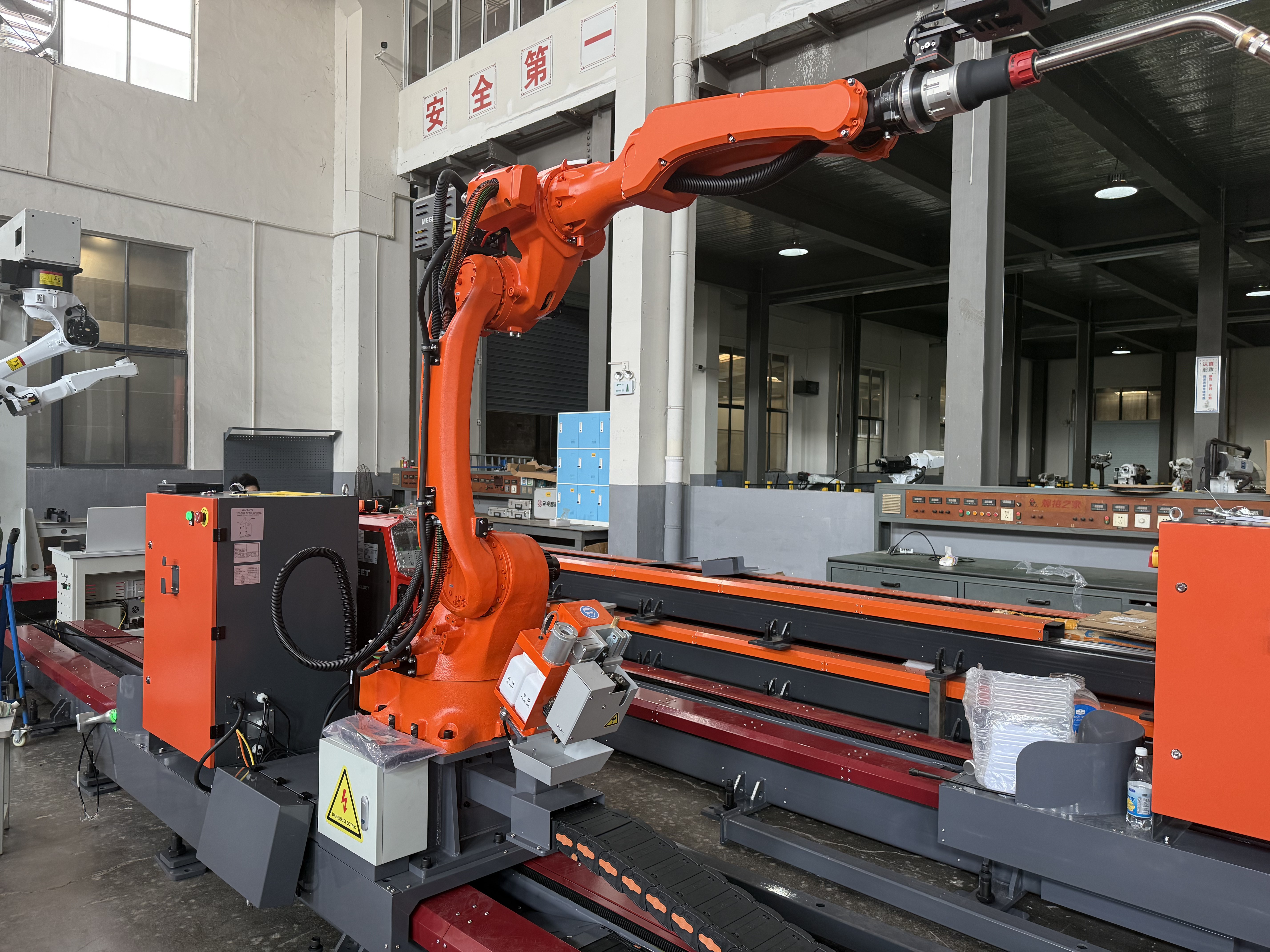
When repetitive MIG joints begin to show scattered metal droplets, the problem is rarely just appearance. Spatter can slow an operator’s work at the unloading station, interfere with paint or coating preparation, contaminate fixtures, and make it harder to judge whether a weld profile is actually acceptable. A Mig welding robot reduces spatter primarily by removing the small, repeated changes in torch angle, stick-out, travel speed, arc length, and joint tracking that occur during manual welding.
The practical answer is that robotic welding lowers spatter when the programmed motion, power source settings, wire delivery, shielding gas coverage, and joint condition are stable together. A robot cannot compensate for every poor setup, but it can repeat a proven setup with much tighter consistency than a hand-held torch. The goal is not simply to “turn down” spatter; it is to establish a stable arc transfer condition and keep the torch in that condition from the first part to the last.
Why repeated joints can create a spatter problem
In a production cell, identical brackets, frames, housings, or fabricated sections may pass through the same welding sequence hundreds of times. The weld program may look correct during the first inspection, yet spatter can gradually increase later in the shift. Operators often see this as a robot issue, but the visible droplets usually come from instability somewhere in the welding system.
Spatter forms when molten metal is expelled from an unstable arc or from repeated short circuits that do not clear cleanly. Excessive current for the selected wire and transfer mode, incorrect voltage, inconsistent wire feed, contaminated contact tips, poor grounding, and incorrect torch distance can all contribute. With a manual process, a welder may instinctively correct a changing arc by adjusting hand position or travel. A robot repeats its commanded path exactly, so a small change in the actual workpiece location or torch condition can continue affecting every cycle until it is corrected.
This repeatability is also the robot’s major advantage. Once the source of instability is identified, the same solution can be held consistently across the batch instead of relying on individual technique.
Stable torch geometry is one of the biggest gains
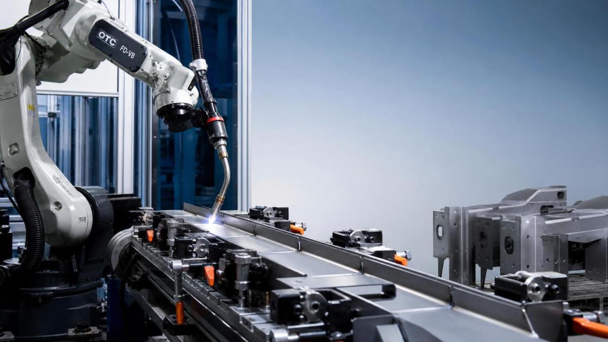
A welding robot maintains a programmed work angle, travel angle, and contact-tip-to-work distance throughout a joint. These details have a direct effect on the arc. When the torch is too close, the wire can repeatedly dip into the weld pool, creating erratic short circuits and a rough, spattery bead. When it is too far away, arc voltage characteristics change, shielding gas coverage may weaken, and penetration can become inconsistent.
For repetitive fillet welds, a fixed work angle helps direct heat into both members of the joint. A drifting angle can favor one side, alter puddle behavior, and leave droplets along the toe of the weld. The robot also holds travel angle more consistently than an operator who must reach around fixtures, rotate the wrist, or manage fatigue during a long run.
That does not mean every job should use one generic torch position. The proper angle and stick-out depend on joint type, material thickness, wire diameter, weld position, and the transfer mode selected. The useful approach is to qualify a position that produces a calm arc and then protect that geometry through accurate fixturing, collision recovery checks, and routine torch maintenance.
Programmed speed prevents the arc from being pushed out of balance
Travel speed affects how long the arc acts on each area of the joint. A robot’s controlled speed helps prevent the uneven heat input that can occur when manual speed varies near corners, tack welds, or awkward access points. Moving too slowly may create an oversized pool, increase the chance of burn-through on thinner material, and allow the wire to interact poorly with the puddle. Moving too fast can leave insufficient fusion, produce an inconsistent bead shape, or force operators to raise settings in a way that makes the arc less stable.
In a robot program, speed should not be treated as an isolated number. It must be balanced with wire feed speed, voltage, inductance or waveform controls available on the power source, and the desired weld size. A stable procedure usually shows a consistent arc sound, predictable bead width, and limited droplet accumulation around the joint. If spatter appears only at starts, stops, corners, or direction changes, the straight-line travel speed may be correct while the programmed transitions need attention.
Watch the start and finish separately
A joint can look clean through most of its length but still leave concentrated spatter at the ignition point or crater. This often points to start parameters rather than the main welding settings. Robots can use controlled wire approach, run-in speed, start current or voltage, and burnback settings to reduce the violent arc initiation that throws droplets onto nearby surfaces.
At the end of the weld, an unsuitable crater fill sequence or excessive burnback can leave an irregular wire end. That wire end may produce a poor restart on the next cycle. Reviewing the first few millimeters and last few millimeters of several consecutive parts is more useful than judging only the center of the bead.
Wire feed consistency matters more than a higher setting
Wire feed speed determines the amount of filler metal entering the arc and is closely tied to welding current in conventional MIG welding. A robot can command the same wire feed rate every cycle, but it cannot make worn feed rolls, an incorrect liner, a damaged cable, or a contaminated contact tip behave consistently. These mechanical restrictions create pulses or drag in the wire path, which may appear as popping, fluctuating arc length, and random spatter.
Before changing the program, inspect the consumable system. Confirm that the drive rolls match the wire type and diameter, the wire spool turns without excessive resistance, and the liner is clean and properly cut. Examine the contact tip for wear, blockage, or a loose fit. A worn tip can allow the wire to wander before it exits the torch, changing the real electrical stick-out even when the robot’s path remains correct.
- Check that wire feeding is smooth during both low-speed starts and normal welding speed.
- Replace damaged or heavily coated contact tips rather than compensating with voltage changes.
- Keep the torch cable path free from tight bends that add drag during robot movement.
- Verify that the programmed wire feed and the actual power-source response match the approved procedure.
Making large parameter changes before checking wire delivery can hide the original fault. It may reduce visible spatter for a short time while creating poor fusion, excess reinforcement, or an unstable condition when the consumables degrade further.
Choose an arc mode that fits the joint, not just the fastest cycle
Different MIG transfer modes produce different spatter behavior. Short-circuit transfer is commonly useful for thin materials, root passes, and out-of-position work, but it can generate more spatter if voltage, inductance, wire feed, and arc control are not matched. Spray transfer can provide a smoother arc and lower spatter in suitable flat or horizontal applications, although it generally requires the correct current range, shielding gas, and heat-tolerant joint design.
Some power sources provide controlled short-circuit or pulsed modes that manage current during metal transfer more precisely. These can be helpful where the joint needs lower heat input while maintaining a stable arc. Their benefit depends on proper setup: selecting a sophisticated waveform does not correct poor fit-up, a dirty nozzle, or a moving part in the fixture.
Fixtures and joint preparation determine whether repetition helps
A robot can repeat a path precisely, but it cannot correct a seam that moves from part to part beyond the available tracking tolerance. Gaps, inconsistent tack placement, burrs, oil, mill scale, rust, moisture, and coating residue can disturb the weld pool and create spatter. A joint that fits well on one component but opens slightly on the next may require different arc behavior even though the program is unchanged.
Fixture condition deserves the same attention as welding parameters. Locate parts from functional datums where possible, keep clamping surfaces clean, and inspect for heat distortion or loosened locating elements. A loose component may shift only when the arc begins or when the robot changes direction, producing a spatter pattern that seems random until the fixture is checked.
For fabricated pipe and plate assemblies, cleaner, repeatable edge preparation can reduce variation before welding begins. Where the application requires milling, controlled bevel geometry, and automatic clamping, a Pipe Cutting & Beveling Machine may support more consistent joint edges. Its stated bevel angle adjustment range of 0° to 90° and thickness capability of 6–80 mm are relevant only when they match the fabrication requirement; the important welding benefit is stable fit-up, not beveling for its own sake.
Shielding gas and nozzle condition should be checked at the cell
Even a well-programmed robot will produce excess spatter if the weld pool is not adequately shielded. Gas flow that is too low may allow atmospheric contamination, while unnecessarily high flow can create turbulence and pull surrounding air into the shielding zone. Leaks at fittings, damaged hoses, blocked diffusers, and buildup inside the nozzle can all disrupt coverage.
Look at the nozzle after a realistic number of cycles, not only when it has just been cleaned. Spatter buildup can narrow the gas path and change the effective distance between nozzle and workpiece. A torch cleaning or reaming station can help maintain repeatability, but its tool condition and alignment must also be checked. An aggressive or poorly aligned cleaning action can damage consumables and introduce the very instability it is meant to prevent.
A practical way to tune a repetitive joint
When a cell produces excessive spatter, avoid changing multiple variables at once. Start with a sound reference part and a clean torch. Confirm part location and joint condition, then observe the actual arc rather than relying only on the programmed values displayed on the controller.
- Inspect the weld location for fit-up changes, contamination, tack position, and clamp movement.
- Check the contact tip, nozzle, diffuser, liner, drive rolls, grounding connection, and gas path.
- Verify the real torch angle and stick-out at the joint, especially at corners and near programmed transitions.
- Compare wire feed, voltage, travel speed, and arc mode with the established weld procedure.
- Make one controlled adjustment, weld several representative parts, and inspect the complete joint rather than one section.
- Review starts, stops, and the next-cycle restart before approving the change.
This sequence protects weld quality. Spatter reduction should not be accepted if it comes with reduced penetration, incomplete fusion, poor bead placement, or unacceptable distortion. The cleanest-looking weld is not automatically the best weld; the required joint performance and the applicable procedure requirements remain the priority.
When robot programming is not the real correction
Repeated teaching changes are sometimes used to chase spatter that is actually caused by variation upstream. If the robot path has not changed but the weld suddenly becomes noisy, inspect consumables, gas delivery, grounding, wire condition, and part fit-up before rewriting points. Likewise, seam tracking may help with gradual location variation, but it is not a substitute for a fixture that allows parts to shift unpredictably.
A Mig welding robot is most effective when it is treated as part of a controlled welding cell: prepared joints arrive in a repeatable position, the wire and gas system remain stable, consumables are maintained, and the program is adjusted from observed arc behavior rather than guesswork. Under those conditions, robotic repeatability turns a clean weld setting into a repeatable production result with less spatter and less downstream cleanup.
