




— —
How Can You Check T-Beam Alignment During a Machine Trial?
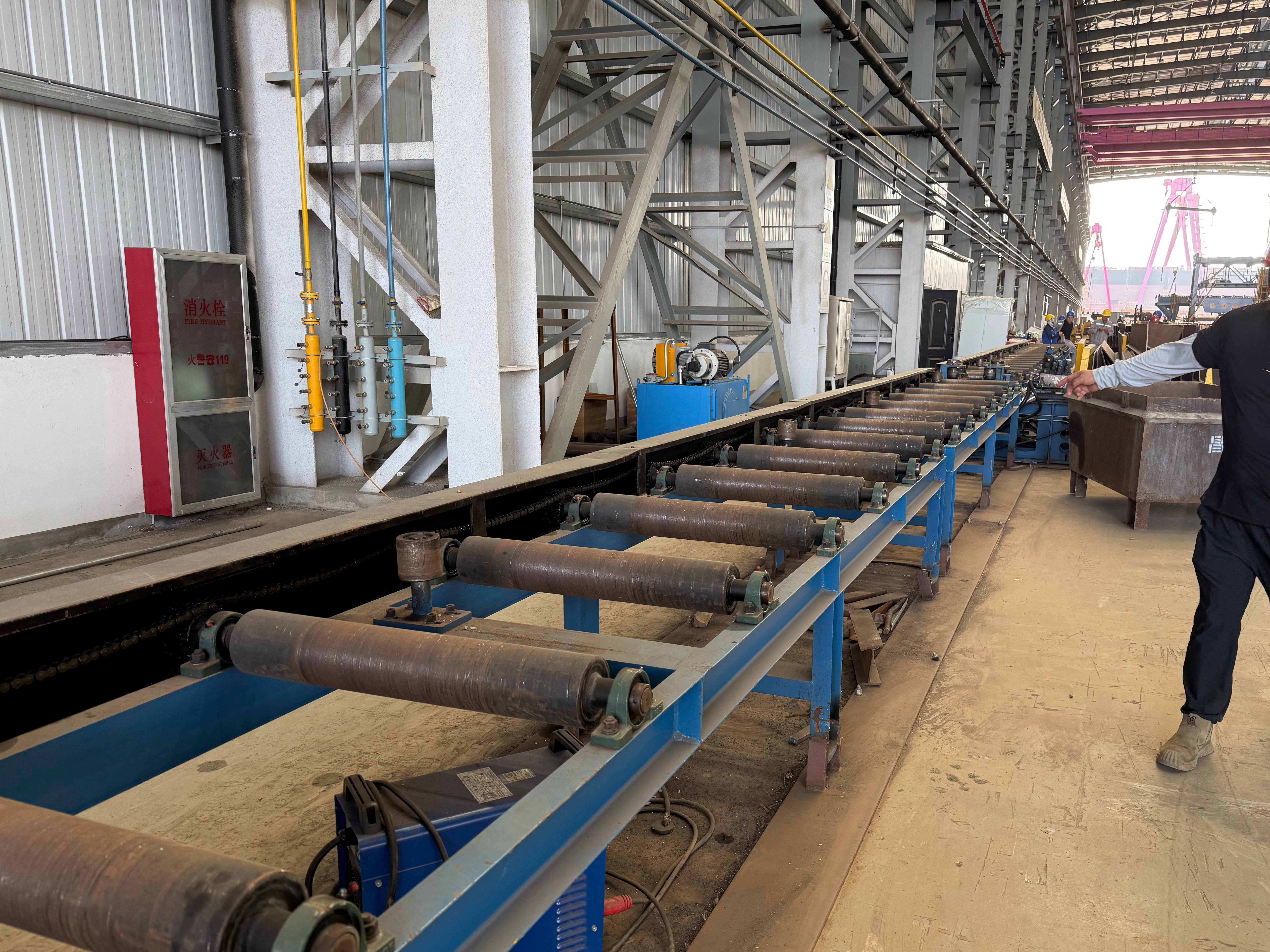
Check T-beam alignment at three points during a machine trial: while the web is positioned against the flange, immediately after tack welding, and after the beam has been released from the machine. A joint that looks centered under the guides can shift during tacking or spring out of alignment when clamping pressure is removed.
The most useful measurements are web position on the flange, web-to-flange perpendicularity, longitudinal straightness, and any twist or distortion. Compare them with tolerances agreed before the trial, using material dimensions and operating conditions representative of the intended production work.
Set the reference points before running the machine
A T-beam consists of a web plate joined to one face of a flange plate. In a symmetrical assembly, the web is intended to sit on the flange centerline. Some designs require an offset web, so do not assume that equal flange projections are always the target.
Agree on the dimensions to be checked and how each will be measured. A useful trial record identifies the flange face used as the reference, the intended web position, the measurement stations along the beam, and the permitted deviations. It should also state whether acceptance applies to the tack-welded assembly, the finished welded beam, or both.
For a centered web, the projections on either side provide a practical check. If the flange width is B, the web thickness is t, and the measured projections are p1 and p2, the web center offset is approximately:
Center offset = (p1 − p2) / 2
This assumes the measurements are taken square to the web from the actual flange edges at the same cross-section. Compare the result with the specified offset, not simply with zero. If plate edges are irregular or the flange has been cut out of square, edge-to-web measurements can mix material errors with assembly errors. Establish a reliable reference line when the drawing or inspection procedure requires one.
Before loading, inspect the plates for obvious bow, twist, edge damage, burrs, and variation in width or thickness. Record any significant condition. A trial performed with distorted incoming plates can still be useful, but the finished result should not be attributed to the machine alone.
Watch how the web is positioned and held
During setup, observe whether the web seats consistently on the intended flange face and whether the locating and clamping devices contact the plates as intended. The web should not be forced into position by an uneven edge or held at the correct location only at the entry point.
Check alignment at the leading end before travel starts, then observe it as the assembly advances. Depending on the machine layout, guides may locate the flange, the web, or both. Look for changes in contact, visible sideways movement, or a web that lifts away from the flange. A gap at the joint can affect both alignment and tack formation.
Pay particular attention to transitions into and out of the active guide or clamp area. The leading and trailing ends may have less support than the middle of the beam. A machine can hold a stable position during steady travel yet allow an end to move as the plate enters or leaves the locating system.
Observe the sequence as well as the final position. If an operator repeatedly corrects the plates by hand before each tack, record that intervention. Manual adjustment may be acceptable for a particular process, but a result achieved through repeated correction should not be treated as evidence of unattended alignment control.
Only trained personnel should make adjustments or take close measurements. Stop and isolate the machine as required by its procedures before placing hands or instruments near moving guides, clamps, or welding equipment. Welding fumes, hot metal, and arc exposure must also be controlled during the trial.
Measure web position at more than one station
Once the beam is safe to handle, measure the web position near both ends and at several intermediate locations. Use the same reference method at each station. For longer beams, add stations where there is a visible change in contact, a tack-related movement, or a suspected bend.
A single measurement at the end cannot establish alignment along the full length. The web may be centered at both ends but drift to one side in the middle, or it may maintain a nearly constant offset while remaining straight. Those results point to different causes:
- A nearly constant offset suggests a setup or reference-position issue, provided the flange width and edge condition are consistent.
- An offset that changes progressively along the beam can indicate drift during travel, plate geometry effects, or inconsistent guidance.
- A local change near a tack warrants inspection for movement during clamping or welding, including an open joint or uneven tack placement.
- An end-only deviation calls for closer observation of support and guide engagement as that end enters or leaves the machine.
These patterns are diagnostic clues, not proof of a particular fault. Repeat the measurement and check the incoming plate geometry before changing machine settings. If the flange width varies, record the actual width at each station; otherwise, a projection change may be mistaken for web movement.
Check perpendicularity without relying on appearance
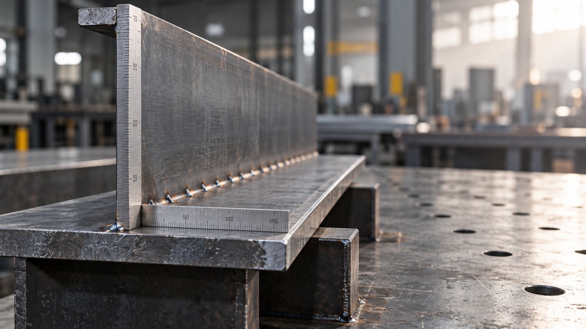
A web can be centered and still lean. Place a suitable engineer’s square against the flange face and the web at the agreed stations. The square must contact clean, accessible surfaces; weld spatter, tack welds, burrs, or a curved flange face can prevent a meaningful reading.
Record the gap between the square and the web at a stated height, or use an angle-measuring instrument where the acceptance method calls for it. State which side of the web was checked and the direction of any lean. A gap measurement is not interchangeable with an angular tolerance unless the measuring height and conversion method are defined.
Measure while the assembly is held only if this can be done safely and the machine permits access. Then measure again after release, at the same stations. A change between the two conditions may indicate springback, residual stress, or movement as the restraints are removed. It does not by itself establish whether the cause is the machine, the material, or the tack sequence.
Also examine the flange. If it is warped locally, a square placed on one part of its surface may give a different result from a square placed elsewhere. The inspection procedure should specify the reference surface and how local plate distortion is handled.
Observe movement during tack welding
Tack welding fixes the relationship between the two plates, but heat and weld shrinkage can also pull them out of position. Watch whether the web remains seated and whether the clamping arrangement restrains it through the tack cycle. Note the tack locations, approximate lengths, sequence, and any manual intervention so the results can be interpreted or repeated.
Compare the position immediately before tacking with the position after tacking and release. If a deviation appears only after welding, inspect the joint fit-up and tack sequence before assuming the guides are inaccurate. Conversely, if the web is already displaced before the arc starts, changing welding conditions alone will not correct the positioning problem.
Check tack quality as part of the alignment assessment. A tack that does not hold the plates together, or one placed where a gap prevents effective restraint, can allow the joint to move during handling. Tack acceptance must follow the applicable welding procedure and project requirements; a visually neat tack is not a substitute for the required weld-quality checks.
Do not confuse tack-welded geometry with final welded geometry. Subsequent welding can introduce additional shrinkage and distortion. If the machine trial ends at tack assembly, report the measurements as tack-assembly results rather than claiming they represent the final welded beam.
Check straightness and twist after release
Support the beam safely at agreed locations without forcing it straight. Use an appropriate straightedge, taut line, laser reference, or other suitable method to measure deviations over a defined length. Record the support arrangement, measurement span, and direction of deviation so results can be compared between runs.
Check the relevant directions specified on the drawing or inspection plan. A beam can have lateral sweep, vertical bow, or both. Web position relative to the flange and overall beam straightness are separate characteristics: a web can remain centered on a flange that is itself bowed.
Twist also needs a defined reference. Compare cross-sections at different positions using suitable levels, angle instruments, or a fixture, with the beam supported consistently. Do not infer twist solely from a web that appears to lean at one end; local flange distortion or an uneven support surface can produce a similar impression.
Where incoming plates were measured before the run, compare their recorded shape with the assembled beam. This helps separate pre-existing material condition from changes associated with positioning, restraint, tacking, and release. It may not isolate every cause, but it prevents a clean-looking machine run from being judged on an unsupported assumption.
Use repeated runs to judge the result
One acceptable beam shows that the setup can produce an acceptable result once. It does not establish repeatability. Run multiple representative assemblies under the agreed conditions, recording plate dimensions, machine settings, travel and tack sequence, operator adjustments, and measurements at the same stations.
If the intended workload includes materially different plate sizes or thicknesses, agree which combinations will be tested. A trial at one convenient size does not demonstrate alignment performance across the machine’s entire stated range. Changes in plate stiffness, weight, edge condition, and available guide contact can affect the result.
Review the measurements against the agreed limits rather than an unspecified claim that the beam is “straight” or “square.” Separate results obtained after normal setup from those requiring repeated intervention. If a dimension fails, retain the measurement pattern and trial conditions, correct the suspected cause, and repeat the run rather than judging the machine from a single adjusted beam.
A useful acceptance record therefore shows not only whether each beam passed, but how it was produced and measured. The strongest result is consistent alignment through positioning, tacking, and release, demonstrated on representative material with corrections and limitations made visible.
