




— —
When is a 7 axis welding robot better than a six-axis model?
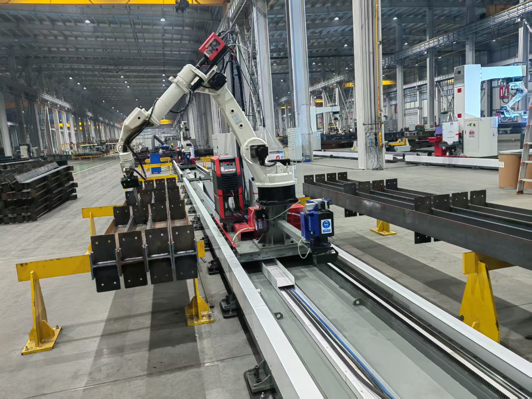
A seventh axis is better than a conventional six-axis welding robot when the welds are difficult to reach from a fixed robot position and the cost of moving, reclamping, or manually finishing the workpiece is greater than the cost and complexity of the added axis. The extra axis is usually a linear travel track, although some systems use a coordinated positioner as the additional motion axis. Its main value is not “more robot movement” by itself; it is maintaining a stable welding posture across a larger or more complex working envelope.
This decision often appears during technical evaluation of long frames, structural assemblies, pressure-vessel components, large machine bases, or fabricated parts with welds on several faces. A six-axis robot may be able to reach each joint individually, yet require repeated fixture changes, robot repositioning, awkward wrist angles, or multiple stations. In that situation, a 7 axis welding robot can improve continuity of production and access quality. Where every joint is compact, centrally located, and consistently presented to the robot, the additional axis may add expense without solving a real bottleneck.
The practical difference is work envelope management
A standard six-axis welding robot already has substantial freedom of movement. Its joints allow the torch to approach a seam from different angles, hold a travel angle, manage wire orientation, and avoid some obstructions. The limitation is that its base remains fixed. As the seam moves farther from the center of the robot’s reach, several problems can appear: wrist joints approach their limits, the arm crosses itself, cable packages become stressed, and the torch angle becomes less suitable for the weld.
Adding a linear seventh axis changes the location from which the robot works. Instead of forcing the arm to stretch toward a distant weld, the robot can travel along a track and keep the arm in a more favorable part of its workspace. This matters because a weld path that is technically reachable is not necessarily a weld path that can be executed consistently.
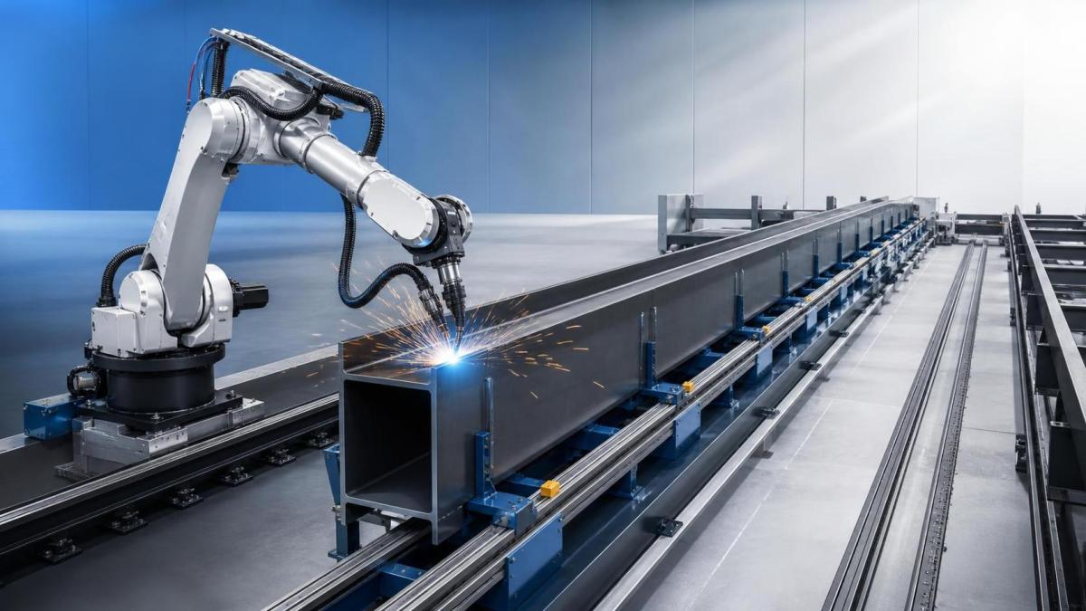
For example, a long longitudinal seam on a fabricated beam may be within the maximum reach of a six-axis arm from one end of a fixture. However, the torch may have good access only near the middle of the beam. At each end, the robot may be forced into a near-limit configuration that changes the contact-tip-to-work distance, travel angle, or clearance around clamps. A rail-mounted robot can follow the part while maintaining similar arm geometry from one end to the other.
Situations where the seventh axis earns its place
Long parts with repeated weld features
Linear travel is most easily justified when part length exceeds the productive working area of one fixed robot position. Typical examples include structural members, trailers, large fabricated enclosures, pipe racks, machine frames, and welded sections with repeated brackets or stiffeners. Without a travel axis, production may require a long robot reach, multiple robots, a moving fixture, or manual handling between weld zones.
The key evaluation point is not the overall part length alone. Map the actual weld locations and identify whether the same torch orientation must be preserved along the full length. A seventh axis is especially useful when repeated seams are spaced along a straight or gently varying path and can be completed while the robot carriage travels smoothly.
Assemblies that cannot be repositioned easily
Some workpieces are too heavy, too flexible, too large, or too awkward to rotate between welding operations. Moving such assemblies can increase handling time and introduce repeatability issues at the fixture. A robot on a travel track may access multiple weld regions while the component remains clamped once.
This is not simply a convenience issue. Every repositioning step can create opportunities for part distortion, fixture loading variation, datum loss, or missed weld sequencing. Where a part must remain in one controlled orientation to manage distortion or preserve fit-up, moving the robot instead of the workpiece can be the more predictable approach.
Multi-sided joints with access constraints
A seventh axis can help when fixtures, temporary tabs, adjacent components, or product geometry restrict how the robot approaches the seam. The rail allows the robot to choose a different base location before the arm uses its six joints to establish the torch posture. This can reduce the need for extreme wrist rotations and may provide a cleaner path around obstructions.
It is particularly relevant for large box structures, frames with internal partitions, and assemblies where welds occur on both external faces and recessed sections. Still, a rail cannot solve every obstruction. If the torch physically cannot enter a narrow opening, additional travel range will not create access. Torch geometry, fixture design, seam placement, and perhaps a different welding process must be reviewed first.
Cells serving more than one fixture or weld zone
A linear axis can allow one robot to serve separate stations arranged along a production line. This may be appropriate where one fixture is being loaded while another is being welded, provided the safeguarding, interlocks, and production sequence are designed for that arrangement. The benefit comes from increasing the useful working territory of one robot, not from assuming one robot can always replace several independently operating cells.
Cycle analysis is essential here. If the robot spends a significant portion of the cycle traveling between stations, the larger envelope may not translate into higher output. The rail works best when travel is coordinated with a productive weld sequence, rather than becoming a long non-welding transfer after every short joint.
Do not choose the seventh axis only because a part is large
Large workpieces are a signal to investigate extra motion, but they are not a decision by themselves. A rotator, headstock-tailstock positioner, turntable, gantry arrangement, or improved fixture layout can sometimes produce better welding positions than a linear robot track. The central question is: which moving element gives the torch the most stable access while keeping the joint in a weldable orientation?
A long cylindrical shell illustrates the distinction. If the important seam is circumferential, rotating the shell may be more effective than moving the robot along the shell length. The robot can then maintain a preferred downhand welding position while the workpiece turns. If several longitudinal seams, attachments, and end details must be welded across the full shell length, combining suitable workpiece rotation with robot travel may be justified.
Fabrication cells handling rolled plate components should evaluate forming accuracy and downstream weld fit-up together. Where cylindrical or conical sections are produced before robotic welding, a Mechanized bending machine with 3 roller can be relevant upstream because it rolls sheet material into cylindrical, conical, arc-shaped, or elliptical forms. Stable rolling accuracy can reduce variation in seam gap and alignment before the part enters the welding fixture. That does not replace robotic path planning, but it can reduce the amount of weld tracking or manual correction required later.
Compare productive reach, not catalog reach
Technical evaluations often begin with a robot reach figure, but maximum reach is a poor substitute for a real accessibility study. At the edge of the envelope, the robot may have limited ability to adjust torch angle, avoid a clamp, recover from part variation, or maintain cable clearance. A robot that can touch the weld point may still be unable to create a robust production path.
A useful comparison should examine each critical seam under realistic conditions:
- Required torch angle, work angle, and travel direction for the intended welding procedure.
- Clearance for the torch body, contact tip, wire feeder hose, sensing devices, and dress-out package.
- Robot joint positions along the entire path, not only at the start and finish points.
- Whether fixture clamps, locating pins, tack welds, and part-to-part variation block the planned approach.
- Ability to perform collision avoidance, wire cutting, torch cleaning, and re-strike operations without leaving the cell.
- Whether the weld can remain continuous or must be divided into segments because of reach limitations.
A rail-mounted system should be assessed with the same discipline. Its carriage travel may extend the workspace, but the track must be long enough to cover approach, weld, and departure positions. The robot cannot begin every weld at the exact end of the rail. Allowance is needed for safe motion, cable routing, carriage acceleration, and maintenance access.
Weld quality depends on coordinated motion
When a robot moves on a seventh axis during welding, the controller coordinates carriage motion with the robot’s arm movement. This can support a consistent TCP path and stable travel speed, but it also makes calibration more important. The relationship between the robot base, rail coordinate system, fixture datum, and workpiece program must be maintained accurately.
Errors in rail alignment or calibration can show up as inconsistent torch-to-joint position over long seams. On a short path, a small reference error may be tolerable. Across a long component, the same error can become more visible, especially where joint tracking is not used or where the weld groove is narrow. The technical review should therefore include how the rail will be installed, referenced, checked, and protected from impact or contamination.
Consider also the cable package. A longer travel axis means a larger motion envelope for welding power, shielding gas, wire, control cables, and extraction connections. Poor routing can create drag, restrict travel, or expose components to spatter and mechanical damage. These details are sometimes treated as installation issues, but they directly affect availability and repeatability.
When six axes remain the stronger choice
A six-axis robot is often the better investment when all required seams lie within a compact fixture area and the arm can reach them with comfortable joint motion. It is also preferable when part families change frequently but do not share a common linear layout. In those cases, a rail may increase programming effort, floor-space requirements, and safety design without delivering a meaningful reduction in handling.
Short, high-mix assemblies are another caution area. If each new product requires a different fixture and only a few short welds, the additional axis may create more path-planning variables than the process needs. A well-designed fixture, a compact positioner, or two simpler stations may provide a clearer operational result.
Build the decision around the difficult seams
Do not base the selection on the easiest welds. Identify the seams that currently create manual intervention, awkward fixture design, segmented robotic paths, or unstable welding orientation. These are the locations most likely to justify the added axis. A useful simulation or offline programming review should include the real fixture envelope, likely clamp locations, tool center point, torch dimensions, and the full range of part tolerances.
Then compare alternatives by process effect: How many times must the part be moved? Can the weld remain in the preferred position? Does the robot retain enough joint freedom for recovery and path adjustment? Is travel time productive, or is it merely transit? The answer will show whether the seventh axis is addressing a genuine constraint or only enlarging a workspace that was already adequate.
In practical terms, choose the seventh axis when it preserves weld access and torch posture across a part that a fixed-base robot can only serve through compromise. Retain six axes when the fixture can present all critical joints within a stable, comfortable envelope. The added axis is most valuable when it removes a repeatability or handling problem from the welding process, not when it is added simply because it appears more capable on paper.
