




— —
Space Frame Welding Machine Capacity: Matching Automation to Node Complexity
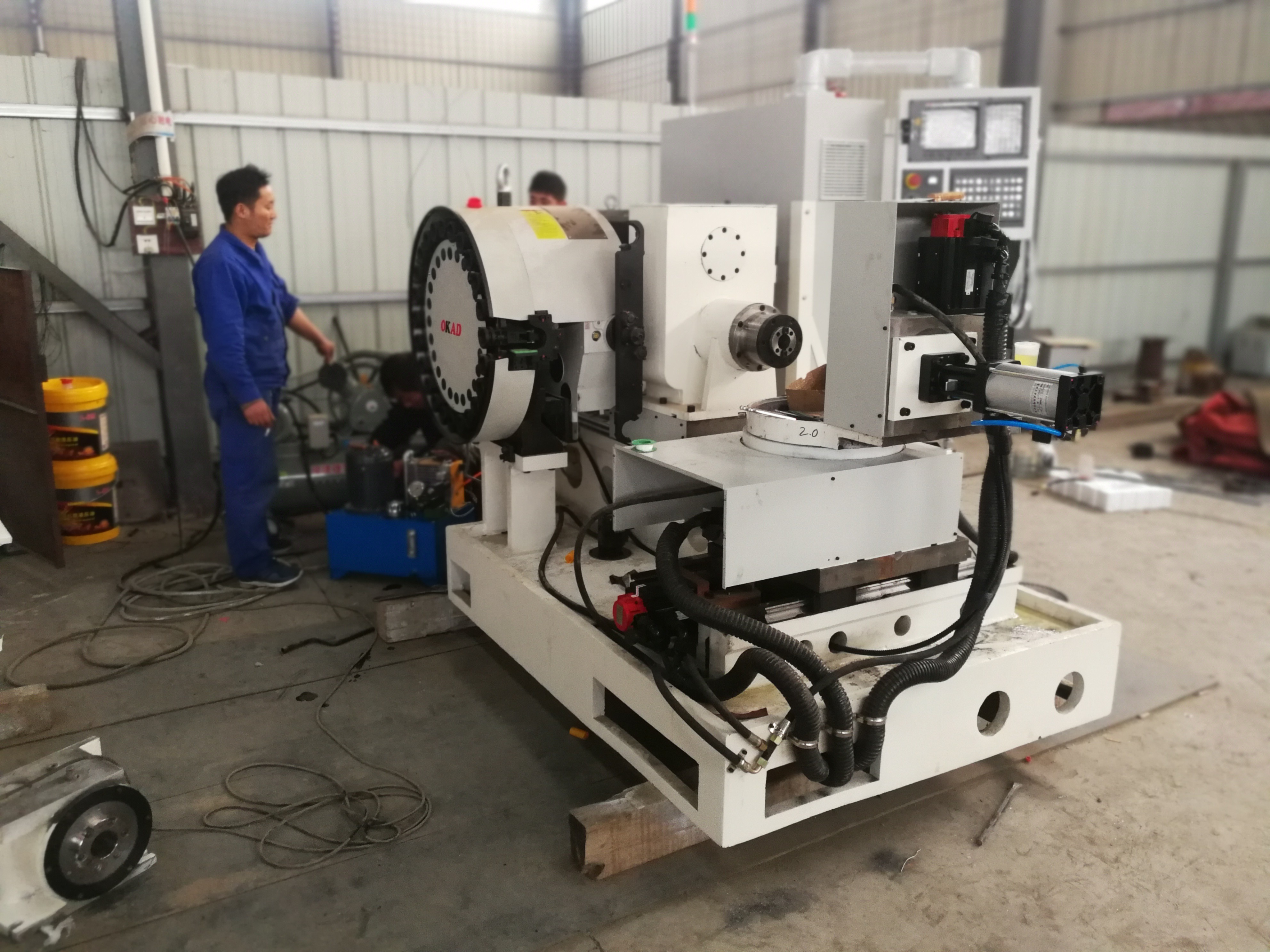
Capacity Starts With the Node, Not the Robot
A Space frame welding machine should be sized around the most demanding node family in the production mix, not around the average tube diameter or the longest member alone. This distinction matters because a space-frame structure may contain many repetitive, accessible welds alongside a smaller number of high-angle, multi-member joints that consume most of the fixture time, robot motion time, and inspection attention.
For a technical evaluator, “capacity” has at least four meanings: the physical envelope that can be handled, the number and range of welding axes, the system’s ability to reach every specified weld, and the number of acceptable assemblies it can produce per shift. A machine can be large enough for the workpiece yet still be under-capable if it cannot present difficult joints at suitable welding angles. It can also have many axes and a large travel range but deliver disappointing output because loading, clamping, programming, or rework dominates the cycle.
The practical selection question is therefore: what degree of automation can accommodate the geometry, variation, and quality requirements of the nodes without creating an unnecessarily expensive and underutilized production cell?
For relatively standardized spherical or conical node assemblies, a purpose-built automated system with controlled positioning may provide a strong balance of repeatability and throughput. For fabricated nodes involving multiple intersecting pipes, variable bevels, changing branch angles, or large structural modules, the evaluation must shift toward reach, reorientation capability, fixture strategy, and offline programming discipline. The more the node changes from job to job, the less useful a simple “parts per hour” claim becomes.
Classify Node Complexity Before Comparing Machine Capacity
Many purchasing discussions begin with a request for welding current, robot brand, rail length, or number of axes. Those details matter, but they become meaningful only after the parts have been grouped by welding difficulty. Two structures of similar overall dimensions can impose very different demands on automation.
A useful first step is to divide the expected workload into node families rather than treating all space-frame work as one category. The categories should reflect actual fabrication conditions: member diameter combinations, joint angles, wall thicknesses, groove preparation, access around the joint, tolerance stack-up, and whether the part can be rotated or repositioned during welding.
Node complexity does not always rise in a straight line with the number of members. A six-member joint built from standard tubes at repeatable angles may be easier to automate than a three-member joint with an unusual branch angle, partial access, and inconsistent preparation. Similarly, a weld that looks simple in a 3D model can become difficult after fixtures, supports, clamps, and neighboring members occupy the available space.
Technical teams should examine representative 3D models with the intended tooling concept in mind. The purpose is not only to prove that a torch can theoretically reach the weld line. The review should test a complete welding posture: torch angle, stick-out, cable clearance, collision margin, approach path, retreat path, and the ability to maintain process stability around the whole joint. A simulation that reaches the start and finish points but relies on marginal clearance is not a reliable production plan.
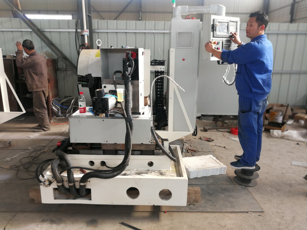
Physical Envelope Is Only the First Capacity Limit
Machine brochures often describe maximum length, width, height, rail travel, and payload. These values are necessary for screening, but a technical evaluator should distinguish the nominal work envelope from the productive envelope.
The productive envelope is smaller because the workpiece must be supported, clamped, accessed, and unloaded. Large structures also need room for lifting equipment, safe operator access, weld cleaning, visual inspection, and occasional manual intervention. If a gantry system is specified close to the maximum dimensions of the intended work, there may be insufficient clearance for fixture features or robot motion near the edges. The result is often an awkward workflow in which large parts fit physically but cannot be welded efficiently.
For long space-frame sections, the support strategy deserves the same attention as robot travel. A long assembly can move or deflect after lifting, during clamping, or as heat accumulates. The robot may then follow the programmed path accurately relative to its own coordinate system while the real joint has shifted. Increasing robot sophistication does not correct a weak support arrangement.
When the production mix includes workpieces longer than a standard fixture bay, evaluators should ask several practical questions:
- Can the component be supported at enough points without blocking torch access?
- Does the fixture establish repeatable datums along the full length, or only at one end?
- Can the machine weld in sections without losing coordinate consistency?
- Will lifting and repositioning introduce distortion or create a new setup reference?
- Does the required process sequence create heat concentration in one area of the structure?
These questions often reveal whether capacity should be increased through a longer gantry, a modular fixture layout, a positioner, or a different division of work between automated and manual stations. A larger machine alone is not necessarily the answer.
Axis Count Must Solve a Real Access Problem
Higher axis count can improve access to multi-angle nodes, but it should not be treated as an automatic indicator of better space-frame welding capability. Extra motion axes are valuable when they allow the torch to maintain acceptable orientation while the workpiece geometry changes. They are less valuable when the underlying limitation is poor fit-up, inaccessible fixture design, or a part that should be rotated rather than approached from an increasingly complex robot posture.
A conventional robot may handle straightforward external circumferential welds effectively where components are presented in a consistent orientation. As the weld path moves around inclined branches, irregular fabricated nodes, or large modules that cannot be easily turned, the system may need coordinated movement across gantry travel, robot joints, and additional positioning axes. The aim is to keep the welding process in a stable operating window, rather than accepting excessive torch-angle variation simply to avoid a repositioning step.
The relevant engineering question is: which motions must occur during welding, and which can occur between welds? Continuous coordinated motion is justified when it protects arc stability, access, or deposition consistency along a difficult path. If the same result can be obtained by indexing the workpiece between welds, a positioner or fixture change may be more economical and easier to maintain.
This is where a multi-axis gantry arrangement can be appropriate for large, varied assemblies. For example, an 9 axis gantry type welding robot is configured for one robot with nine CNC axes and is intended for substantial work envelopes, including workpieces extending beyond 12 meters and below 25 meters in the stated ground-rail arrangement. Its value in a space-frame application would depend on whether those axes resolve actual torch-access and travel requirements for the node set, rather than simply adding flexibility on paper.
During evaluation, request a path review for the difficult nodes, not only a demonstration on an open test coupon. The review should include the welds that are closest to supports, the joints with the steepest branch angles, and those likely to require multiple passes. A system that performs well on the easiest seam may say little about the bottleneck that determines total capacity.
Throughput Is Governed by the Full Cell Cycle
A space-frame welding cell does not produce output only while the arc is on. Its effective capacity includes material handling, positioning, clamping, model preparation, program selection, fit-up verification, welding, cooling where required, inspection, unloading, and recovery from exceptions. Arc-on time is important, but it is not a complete productivity measure.
This is especially relevant for low-volume, engineer-to-order fabrication. If every assembly requires a new fixture layout and extensive program preparation, adding a faster robot may have limited impact. Conversely, in a repetitive project with consistent node geometry, reducing setup time and enabling stable automatic welding can produce a meaningful improvement even if the raw deposition rate remains unchanged.
Technical evaluators should map the expected cell cycle before selecting a capacity level. The map does not need speculative production figures. It should identify which steps are automated, which require skilled manual input, and where parallel work is possible. For example, a cell may weld one assembly while the next is being fitted on a separate fixture, or it may require the same platform for both fitting and welding. Those are fundamentally different capacity models.
A useful review separates time into four groups:
- Preparation time: import or verify the model, assign welds, select process parameters, and prepare consumables.
- Part presentation time: lift the workpiece, locate it against datums, clamp it, and confirm access conditions.
- Welding time: robot travel, seam tracking, arc starts and stops, interpass actions, and any required repositioning.
- Release time: visual checks, dimensional confirmation where specified, unclamping, unloading, and fixture reset.
Capacity problems are frequently hidden in part presentation time. A high-output robot cannot recover lost minutes caused by difficult crane access, clamps that need repeated adjustment, or tube assemblies that arrive with inconsistent fit-up. The best automation plan may therefore include modest investment in upstream cutting accuracy, coping quality, and fixture discipline before increasing robot capability.
Systems that can import 3D drawings, extract or select weld information, and match welding processes can reduce programming burden for repeatable work. However, model-driven operation still depends on the relationship between the digital model and the physical assembly. A nominal weld extracted from a drawing does not guarantee that the real joint is placed correctly or prepared within the limits assumed by the welding procedure.
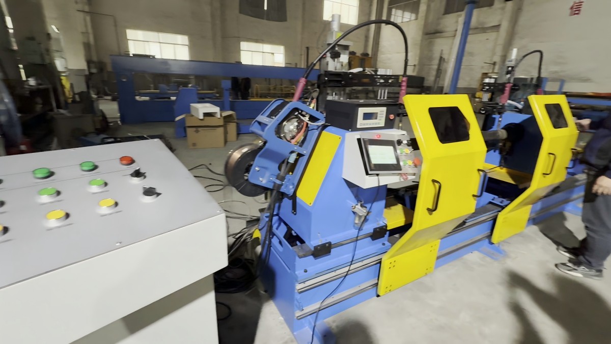
Fit-Up Variation Sets the Boundary for Automation
Automation delivers its strongest results when the incoming structure is sufficiently repeatable. This is not a demand for perfect fabrication; steel structures have practical variation, and capable systems may use sensing or arc tracking to correct for local seam deviation. The important distinction is between correctable variation and variation that changes the joint itself.
Arc tracking can assist the robot in following a seam whose actual location differs slightly from the programmed path. It does not automatically solve excessive root gaps, missing bevel preparation, member end mismatch, severe angular error, contamination, or a node that has been assembled in the wrong orientation. When such issues are common, the welding cell spends time stopping, alarming, being adjusted, or producing welds that require additional inspection.
Before committing to a highly automated Space frame welding machine, assess variation at the handoff from cutting and fit-up to welding. The assessment should focus on the dimensions that affect welding access and joint condition, rather than only overall component length. Examine cut-end consistency, tube ovality where relevant, branch alignment, tack-weld placement, actual gap range, and fixture datum repeatability. These factors determine whether robotic correction is a useful refinement or a substitute for a process that needs attention upstream.
Complex nodes deserve a defined exception path. Some assemblies will fall outside the normal automated envelope because of material deviation, unusual repair work, design revisions, or one-off geometry. A realistic production plan identifies how those parts will be evaluated and processed without disrupting the main cell. Trying to force every exception through a programmed robotic sequence can reduce availability for the repetitive work that justifies the automation investment.
Choose the Automation Level by Mix Stability
There is no universal threshold at which a space-frame fabricator should move from manual welding to a multi-axis robotic cell. The decision is shaped by the stability of the fabrication mix, expected repeatability of assemblies, available skilled labor, quality documentation needs, and the consequences of inconsistency at critical nodes.
Lower-complexity and lower-volume work may be better served by flexible manual or semi-automatic stations supported by accurate fixtures. This approach can be responsive when geometry changes often and setup effort would otherwise dominate. It also allows experienced welders to respond directly to variable fit-up, although results still depend heavily on process control and operator consistency.
Repeatable node families with a predictable loading pattern are well suited to dedicated automation. In this range, the major gains often come from consistent positioning, repeatable torch paths, and less dependence on manual handling of long weld sequences. The equipment should be specified around the workpiece family that will occupy it most often, with enough reserve to handle planned dimensional variation.
Large, multi-angle, or high-volume structural assemblies may justify a gantry robot with extended travel and coordinated axes. That investment makes sense when difficult joints recur often enough that the cell can remain productive, and when the supporting processes can present assemblies consistently. A cell designed for rare maximum-size parts can become an expensive general-purpose station if most daily work does not use its envelope or motion capability.
Evaluators should avoid choosing only between “manual” and “fully automatic.” Intermediate arrangements can be effective: automated welding for accessible, repeated seams; manual welding for restricted joints; separate fit-up and welding fixtures; or a gantry system that operates on a defined family of long assemblies while smaller work remains in another cell. The right boundary is determined by where automation improves the controlled part of the process without being burdened by unavoidable variation.
Specification Questions That Expose Weak Assumptions
A robust technical specification should make the supplier demonstrate capability against real parts and production conditions. Broad claims about robot reach, welding speed, or automatic operation should be translated into verifiable engineering questions.
- Which representative node models will be used for reach and collision review?
- What workpiece dimensions include fixtures, supports, clamps, and loading clearance rather than bare steel dimensions only?
- How is the assembly located, and what references are preserved after lifting and clamping?
- Which welds can be completed in one setup, and which require repositioning?
- What type of seam tracking or sensing is applied, and what level of joint variation can it address?
- How are new drawings converted into robot programs, reviewed, and released to production?
- What happens when a weld cannot be reached or an assembly falls outside normal fit-up tolerance?
- Which safety interlocks, emergency stops, grounding provisions, and machine-status indications are included in the cell design?
These questions also help distinguish useful automation features from features that add complexity without reducing risk. Status indication, fault alarms, accessible emergency stops, and grounding arrangements are basic but important parts of a production cell because a long structural workpiece can make intervention and recovery more difficult than in a compact robotic station. Their value lies in supporting controlled operation and clear response when the normal cycle is interrupted.
The final decision should be based on a capacity model built from the difficult, recurring nodes and the actual work flow around them. A larger envelope, more axes, or faster stated welding speed can be justified, but only when it removes a demonstrated constraint: inaccessible welds, excessive repositioning, unstable orientation, insufficient part travel, or a repeatable throughput bottleneck.
For technical evaluators, the most defensible selection is rarely the most automated machine available. It is the system whose physical layout, motion capability, sensing, fixtures, and operating sequence match the node complexity that will genuinely occupy the shop floor.
