




— —
How tack welding improves alignment in T-beam assembly machines
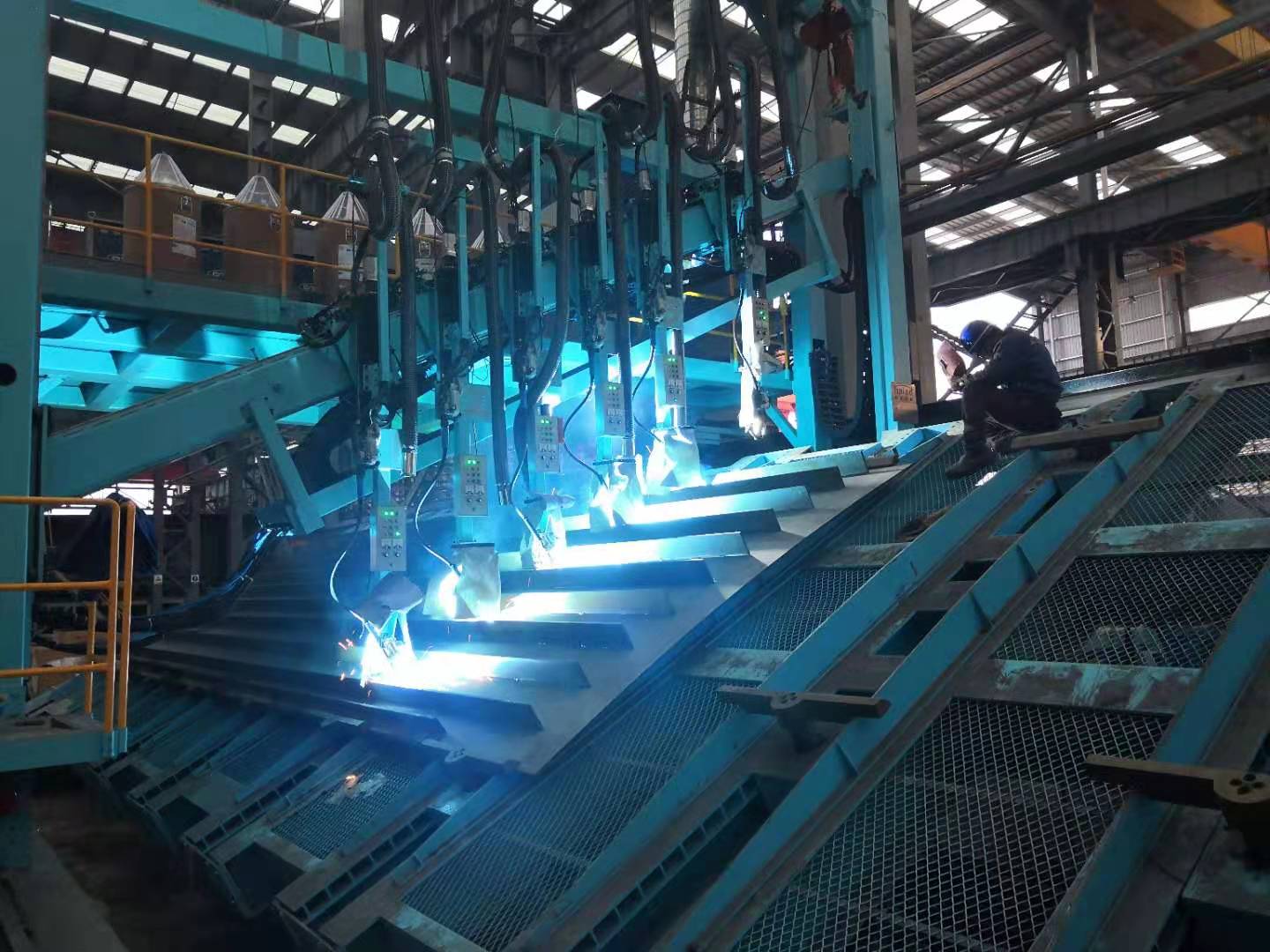
When a web plate is placed on a flange for T-beam assembly, the parts may appear correctly positioned at the loading station but shift as soon as clamps release, the beam advances, or heat is introduced by the main welding pass. Even a small change in web centering, root gap, or squareness can create downstream problems: uneven fillet welds, beam twist, difficult fit-up at the next station, and inspection findings that are expensive to correct after full welding.
A T-beam assembly machine with tack welding improves alignment by fixing the web and flange together at controlled locations before continuous welding begins. The tack welds do not replace final welds; their purpose is to preserve the verified assembly position while the beam is handled, conveyed, and welded. When tack placement, clamping, and fit-up controls are coordinated, the process reduces the opportunity for movement at the point where alignment matters most.
Why alignment becomes unstable before final welding
T-beam assembly looks straightforward because the basic geometry involves only a flange and a web. In production, however, alignment is affected by plate condition, fixture accuracy, thermal input, material handling, and the sequence in which forces are applied. A web that is nominally straight can still move when its lower edge contacts a flange with mill scale, burrs, local waviness, or uneven surface contamination. If one side of the web contacts first, the component may lean slightly even though the machine’s guides are set correctly.
Longer members create another challenge. Their own weight can cause local sag between support points, particularly when flange thickness, web height, or beam length changes from one job to another. A beam may be aligned at the clamping area but deviate slightly before or after that location. Once welding starts, shrinkage forces can pull the web toward one side or create a gradual sweep along the beam length.
Tack welding is valuable because it locks the assembly condition while the parts are still held in the intended position. Without this intermediate restraint, the continuous welding process must overcome movement caused by travel, vibration, thermal expansion, or inconsistent contact between the plates. That is a poor point in the process to discover that the web has drifted from its required centerline.
The role of tack welds in a controlled assembly sequence
A tack weld provides local mechanical restraint. In a T-beam machine, clamps, hydraulic hold-down devices, side guides, and locating surfaces first bring the web and flange into position. The machine should establish the required relationship before any tack is deposited: web position across the flange width, web verticality, contact at the joint line, and the absence of a gap that could affect final fillet weld formation.
Once this position is confirmed, tack welds hold that relationship as the beam leaves the immediate restraint of the fixture. The tack sequence matters because weld metal shrinks as it cools. Tacks placed unevenly on one side, made excessively large, or applied while the web is not fully seated can introduce the same alignment problem they are intended to prevent.
In practice, the objective is not simply to add more tacks. The objective is to apply tacks of a suitable size, spacing, and sequence to prevent movement without creating excessive local heat input or obstruction for the final welding heads. A sound process uses tack welding as part of fit-up control rather than treating it as an informal holding operation.
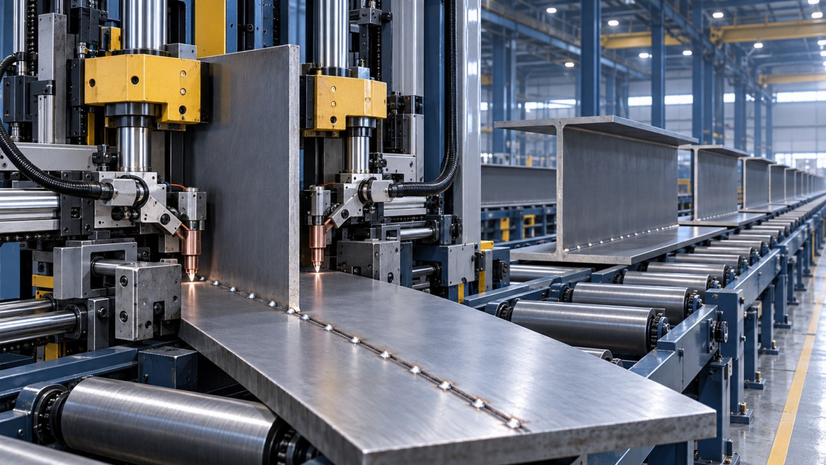
What a properly controlled tack accomplishes
- Maintains the web’s location on the flange during transfer and final welding.
- Reduces the chance of the web opening away from the flange at isolated points.
- Helps preserve a consistent joint condition for automatic fillet welding.
- Limits sudden component movement that can create handling or pinch-point risks during downstream positioning.
- Provides visible points for checking whether the assembly remained stable after it left the clamping zone.
The tack itself should be judged as a production control feature. A cracked, poorly fused, excessively convex, or misplaced tack is not a harmless temporary detail. It can allow movement, interfere with the final weld bead, or become incorporated into a weld area with defects already present.
Fit-up must be correct before the first tack is made
Tack welding can preserve good alignment, but it cannot correct a web that was clamped in the wrong position. Inspectors often find recurring dimensional variation when the process relies on tack welding to “pull” parts together rather than using the machine’s locating and clamping functions to establish fit-up first.
Before the assembly cycle begins, the flange should be checked for excessive bow, twist, edge damage, and surface conditions that prevent stable support. The lower edge of the web should be free from burrs, slag, heavy rust, or attachments that stop it from seating evenly. These conditions do not always cause an obvious gap at the front of the beam; they may create intermittent separation that only becomes visible as the workpiece moves.
The main pre-tack verification points are usually simple, but they must be evaluated at the right locations rather than only at the leading end:
- Confirm that the web is centered or offset according to the drawing requirement.
- Check that the web stands perpendicular to the flange where the machine establishes alignment.
- Verify contact along the joint line and investigate localized gaps before welding.
- Ensure the flange is supported so that its own deflection does not distort the reference position.
- Confirm that clamps contact the workpiece firmly without deforming thin material.
- Review whether guide settings match the current flange width and web thickness.
Measurements should be meaningful for the assembly tolerance specified by the fabrication drawing or applicable project requirements. A machine can repeatedly produce the same error if its guide position or reference point is set incorrectly. Repeatability alone is not evidence of compliance; it only shows that the process is stable around its current setting.
Where tack weld location makes a practical difference
Tack locations should support the forces expected during handling and welding. The leading and trailing areas of a beam often need particular attention because they are exposed to entry, exit, lifting, or conveyor-related movement. At the same time, tacks should not be placed so close to an end that they create an unsuitable termination condition for final welding or interfere with later processing.
Between the ends, spacing needs to reflect the stiffness of the web and flange, the beam length, the transfer method, and the heat input of the final welding process. A thin or flexible web may require closer restraint than a stiff assembly, but increasing tack frequency without considering heat balance can contribute to distortion. The appropriate arrangement is therefore process-specific and should be established through qualified production instructions rather than by a universal spacing rule.
For double-sided fillet weld assemblies, the sequence should also avoid pulling the web toward one side. Balanced tack placement can help maintain the intended vertical position. Where the machine applies tacks from a single accessible side, the clamping system becomes even more important because it must resist the directional effect of the tack weld until the assembly is secure.
Oversized tacks can create their own alignment risk
A common response to movement is to increase tack size. This may temporarily stop a web from shifting, but it can create a new problem. Larger tacks introduce more localized heat, which can cause uneven contraction. They may also require the final welding head to bridge over an irregular profile, especially if the tack contour is high or poorly blended. If the final process does not adequately remelt the tack, discontinuities may remain at the interface between tack and production weld.
The better response is to identify why movement occurred. Possible causes include insufficient clamping force, worn side guides, incorrect workpiece support, contamination at the joint, an unsuitable transfer speed, or a tack sequence that leaves too much unsupported length. Tack size should be controlled within the approved welding procedure, not adjusted casually to compensate for an uncorrected machine issue.
How tack welding affects distortion during final welding
Tack welds influence distortion in two ways. First, they restrain the parts, helping the beam retain its initial geometry while final weld metal is deposited. Second, they are welds themselves and therefore add heat and shrinkage. The quality benefit comes from managing both effects rather than assuming that restraint is always beneficial.
Where the web is firmly seated and properly clamped, moderate tacks can keep the joint stable while the final welding heads establish continuous fillet welds. If the beam enters final welding with uneven root contact or a web leaning to one side, the continuous welds may lock in that error. Rework after full welding can involve heating, mechanical straightening, grinding, reinspection, and renewed handling, all of which increase process risk.
Heat balance is especially important on beams with thin flanges, tall webs, or variable cross-sections. A tack pattern that works on one beam size may not behave the same way on another. Production planning should distinguish between material families instead of assuming that one set of settings applies equally to every flange width and web thickness.
Inspection points that reveal whether the machine is doing its job
Inspection is more effective when it follows the movement of the assembly through the line. Checking only the completed beam can identify a defect, but it may not show whether the original cause was material condition, fixture setup, tack welding, or final weld heat input. A few checks at defined process points make the source easier to isolate.
At loading, confirm that the plates are the intended size and are positioned against the relevant references. At the clamping station, verify web centering and verticality before welding begins. Immediately after tack welding, inspect the assembly for visible movement, incomplete contact, damaged tacks, or changes in position as clamps release. Before the beam reaches final welding, check that transport equipment has not introduced a new misalignment.
After final welding, dimensional inspection should consider more than the appearance of the weld bead. Web offset, flange flatness, angular distortion, sweep, and twist can each indicate different process controls needing attention. A beam may have acceptable-looking fillet welds while still presenting an assembly geometry issue that affects later fabrication or structural fit-up.
Use process trends rather than isolated defects
One nonconforming beam may be related to an individual plate defect or handling event. Repeated deviation at the same location, on the same side, or after a particular machine adjustment is more informative. For example, a recurring lean in one direction may point to guide wear or a misaligned reference surface. Distortion concentrated around regularly spaced tack locations may point to tack size or sequencing. A gap that appears only in longer beams may suggest insufficient intermediate support.
Recording these patterns helps separate material-related variation from machine-related variation. It also prevents an operator from making repeated manual corrections that hide the underlying issue. Manual correction may restore one beam, but it can reduce consistency and introduce new safety exposure if operators must intervene near moving clamps, rollers, or welding equipment.
Safety value of securing the assembly early
Alignment control is also a handling control. An unsecured web can shift unexpectedly when clamps release or when the beam changes from one support point to another. This creates a risk around pinch zones and can make manual guidance tempting at precisely the time when the workpiece should be controlled by the machine and established operating procedures.
Reliable tacking reduces the likelihood of sudden relative movement between the web and flange, but it does not remove normal welding hazards. Access to the tack welding area should remain controlled, and personnel should not reach into the fixture to reposition material while clamps, rollers, or welding functions are active. Any need for frequent manual repositioning should be treated as a process problem requiring adjustment of guides, support, or loading practice.
Workpiece condition also has a safety dimension. Loose scale, burrs, sharp cut edges, and unstable plate stacking can affect both fit-up and safe handling. Addressing those conditions before assembly reduces the chance that the machine must compensate for poor incoming preparation.
When tack welding should trigger a deeper review
A stable tack welding process should hold the verified position without requiring repeated operator intervention. A review is warranted when tacks crack during transfer, the web position changes after clamp release, final weld quality varies at tack locations, or distortion increases after a change in material thickness, beam geometry, or welding parameters.
It is also important to review the approved welding procedure when changing tack size, filler material, preheat practice, or final welding settings. Tack welds may become part of the finished weld zone, so their compatibility with the final process cannot be assumed. The required acceptance criteria, welding sequence, and inspection method should match the fabrication specification governing the beam.
The practical advantage of a T-beam assembly machine with tack welding is therefore not merely faster joining. Its real contribution is process discipline: establish the correct fit-up, restrain it while that condition is valid, verify that the assembly remains stable, and send a controlled joint into final welding. That sequence makes alignment problems easier to detect early, before they become distortion, rework, or handling issues later in the line.
